RS-1_instruction manual.pdf - 第641页
Pa r t 2 D et ai l ed Des c r i pt i o n of Ea c h F unc t i o n Chapte r 6 G e neral - Purpose Vision Co mpone nt 6- 10 ◎ W hen the r adio b utton “ Point ” is s elec ted on t he “ El e m ent G roup ” di alog b ox, the …
Part 2 Detailed Description of Each Function Chapter 6 General-Purpose Vision Component
6-9
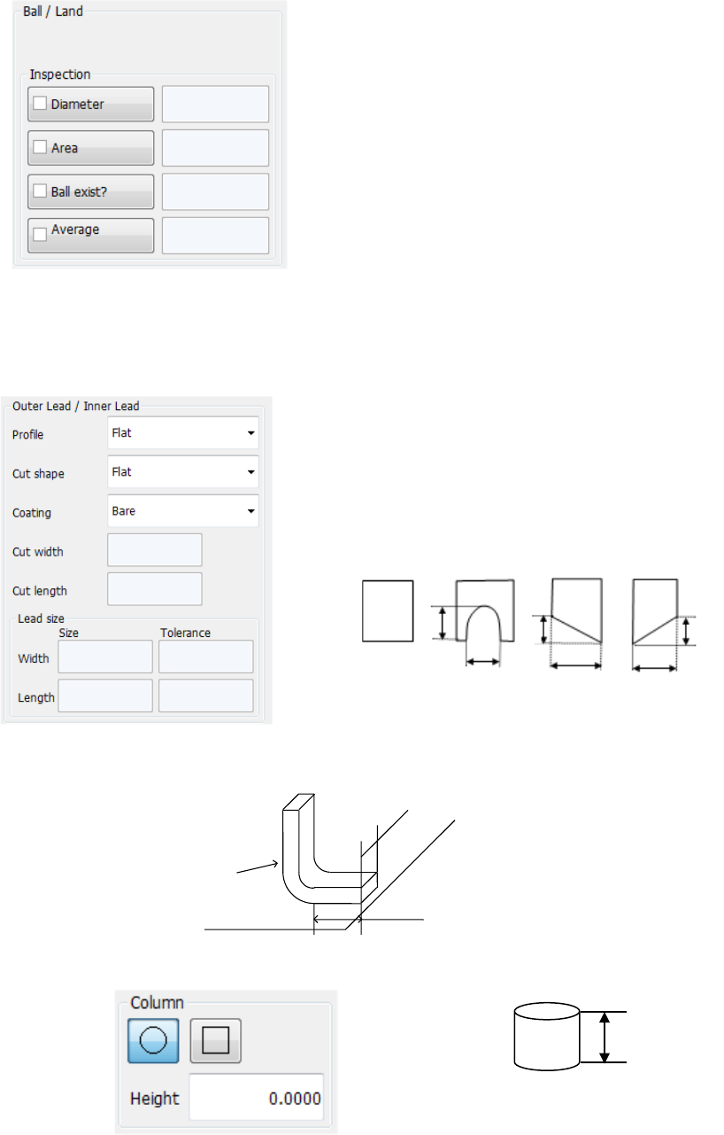
• Ball/Land
When you select “Ball” or “Land” in the “Type” field, these fields appear on the screen.
Select the shape of a ball or land. (However, the system does not distinguish the shape
currently.)
Specify whether to check the shape or not, and enter the judging
level.
− Diameter:
Specify whether to check the diameter. When checked, the
system checks each ball based on the average diameter of all
checked balls.
− Area: Specify whether to check the area.
− Ball exist?:
Specify whether to check that there is a ball or not. The initial
value “30 %” indicates that the system can detect the
condition: 20 % of a ball is cut away.
− Average diameter:
Specify whether to check the diameter with comparing the
average diameter of checked balls and the input diameter
• Outer Lead/Inner Lead
When you select “Outer Lead” or “Inner Lead” in the “Type” field, these fields appear on the
screen.
− Profile: Specify the lead type.
− Cut shape:
Specify the shape of the cut section if the tip of a lead is cut:
− Cut width, Cut length:
When you select “U-shape cut,” “Left bottom cut” or “Right
bottom cut,” enter these fields.
− Coating:
Specify the coating type of a lead. Not used at the present.
− Lead size:
For a gull-wing lead, enter the width and length of the tip of a lead that is in contact with a
board.
• Column
This screen appears when you select “Column” in the “Type” field. Not used currently.
高さ
Height
Flat
Length
U-shape
cut
Width
Left bottom
cut
Right bottom
cut
Width
Width
Length
Length
Width
Lead
Board
Part 2 Detailed Description of Each Function Chapter 6 General-Purpose Vision Component
6-10
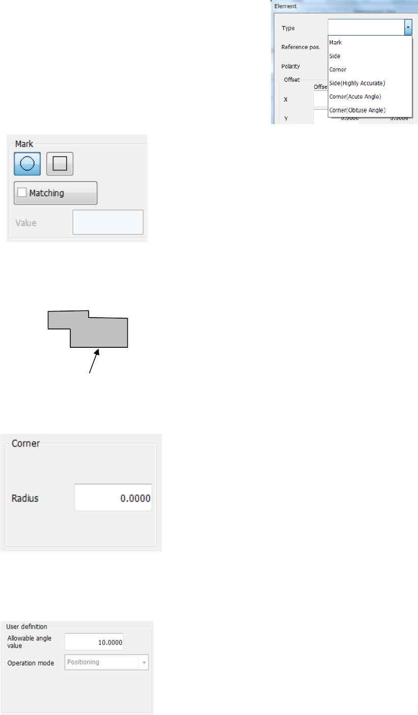
◎ When the radio button “Point” is selected on the
“Element Group” dialog box, the menu items
shown in the right figure can be selected from
the “Type” list.
• Mark
When you select “Mark” in the “Type” field, this screen
appears.
- Matching:
Specify the tolerant range of the similarity.
The higher value you specify, the more strictly the
system judges the similarity.
(The initial value is set to “600.”)
• Side
For a component whose element is irregular-shaped (other than a circle or square),
you can cause the system to recognize a component with its side.
The bottom side is the reference side. When you
use the right side, enter “90°” in the “Theta” field of
the “Offset” menu item displayed on the “First
element position” column. In the same manner,
enter “180°” for the top side or “270°” for the left side.
• Corner
When you select “Corner” in the “Type” field, this screen appears.
- Radius:
Enter the radius of the corner section.
For a right-angled corner, enter “0.”
The reference corner is the bottom left corner when the
component supply angle is 0°.
If you want to use the bottom right corner, specify “90°”
in the “Theta” field of the “Offset” menu item displayed
on the “First element position” column. In the same
manner, enter “180°” for the top right corner or “270°”
for the left top corner.
• User definition
This column is displayed when “User definition” is selected as the “Type.”
• Allowable angle value:
Unless “Direction” is specified in the “Operation mode”
field, enter the allowable angle deviation generated
during recognition here. The entered value is applied in
both directions: positive and negative directions.
(“10 degrees” is entered as the initial value.)
The operation mode can be set when you create a
user-defined element, and you cannot change it on this
screen.
Reference side
Part 2 Detailed Description of Each Function Chapter 6 General-Purpose Vision Component
6-11
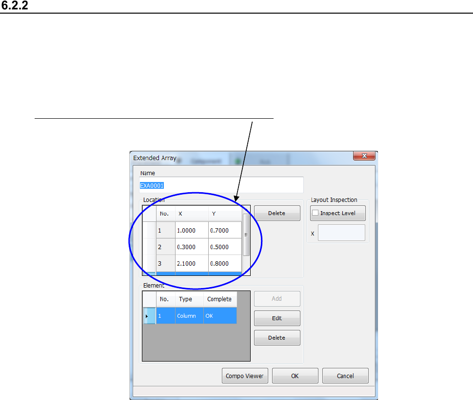
Creating an extended array data format
When you select “Extended array data format” on the initial screen for creating a general-purpose
vision component, the following dialog box appears on the screen.
The procedure for creating data is basically the same as that for the “Element group/ Element
format.” However, for an “Extended array data format,” specify the X and Y coordinates of an
element one by one.
Specify an element in the “Location” field one by one. Enter the X and Y coordinates viewed
from the center of a component.
* Up to 256 locations can be set.