RS-1_instruction manual.pdf - 第368页
Part 1 B asic O peration Chapter 4 Cr eating a Produc tion Progra m 4- 33 3) “Option” group ① Not U sed/Used Select whet her to use th e data set in the “O ption” gr oup or not. Not Used Select this b utton when yo u do …

Part 1 Basic Operation Chapter 4 Creating a Production Program
4-32
③ Sensor delay time
Select whether to set the delay time of each sensor to the same value or not.
Standard Select this button to set the delay time of each sensor to the same value.
Option Select this button to set the delay time of each sensor respectively.
When you select the <Standard> button, the value set in the “Sensor delay” field under the
title “Standard” becomes active. When you select the <Option> button, the delay time set
in the field for each sensor under the title “Option” becomes active.
④ Standard
When you select the “Standard” radio button in the “Sensor delay time” field, set the delay
time or delay length.
The allowable range for each unit is 0 to 2,500 (ms) and 0 to 1,000 (mm).
⑤ Option
When you select the “Option” radio button in the “Sensor delay time” field, set the delay time
or delay length of each of the sensors: the IN sensor, the WAIT sensor, the STOP sensor,
the C-OUT sensor and the OUT sensor.
The allowable range for each unit is 0 to 2,500 (ms) and 0 to 1,000 (mm).
⑥ Ready In delay setting
Normally, when the Ready IN signal (signal for receiving the ejected board to be input from
the post process) is set to ON, the system passes the board to the post process without
stopping the board.
However, when you set this delay time here, the system stops transportation of a board
when the OUT sensor detects it, and then the system rotates the motor again to eject the
board when the Read IN signal is set to ON after the specified time passes. This delay
time is useful for passing/receiving a board between the machines whose board transporting
speeds are different from each other. Note that this delay time starts counting when the
OUT sensor is set to ON.
⑦ Sensor delay when re-clamp
Set a period of delay time or a length when the PWB is not removed and is re-clamped at
the production restart after the production has been completed due to production failure
such as feeder float-up, etc.
Set a value ranging from 0 to 5000 (ms) or 0 to 200 (mm).
2) “Conveyor motor speed” group is explained below.
① Not Used/Used
Select whether to use the settings made in the “Conveyor motor speed” group or not.
Not Used
Select this button if you do not use the settings made in the “Conveyor
motor speed” group.
The motor is operated based on made with the main unit side.
Used
Select this button if you are to use the settings made with the “Conveyor
motor speed” group.
② Transferring PWB
Set the transport speed to carry the PWB to the center buffer.
③ Preceding Process
Set the speed in which the machine loads a board from the previous process until it finishes
loading the board into it completely (until the IN sensor is set to OFF).
④ Next Process
Set the speed for transporting a board on which components are placed to eject it to the
post process.

Part 1 Basic Operation Chapter 4 Creating a Production Program
4-33
3) “Option” group
① Not Used/Used
Select whether to use the data set in the “Option” group or not.
Not Used
Select this button when you do not use the setting made in the
“Option” group. The system operates according to the settings of
the main unit.
Used
Select this button when you use the setting made in the “Option”
group. The system operates according to the board stop setting
made in a production program.
② Hold Wait Sensor active until PWB moves out
Checking on the check box will enable this function.
Checking off the check box will disable this function.
4) “Other” group
① Long-sized board divide position
Enter the size for dividing the component placement area in the X direction if a board is to
be clamped twice. This means that you have to enter the distance from the edge point of
the board layout in the X direction. When the size of a board does not have to cause the
board to be clamped twice, this setting is ignored.
Part 1 Basic Operation Chapter 4 Creating a Production Program
4-34
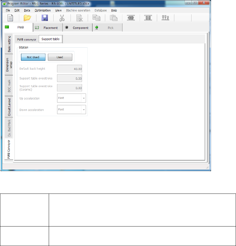
(2) “Support table” screen
If you select the “Support table” tab when the “PWB Conveyor” tab is selected, the following
screen appears.
1) Not Used/Used
Select whether to use the settings in the “Left station” group/“Right station” group or not.
Not Used
Select this radio button if you do not use the settings made in the
“Left station” group or the “Right station” group respectively.
The system operates according to the settings made with the main
unit(“Machine setup” – “Set contents of transport”).
Used
Select this radio button if you are to use the settings made in the
“Left station” group or the “Right station” group respectively.
2) Default back height
This item sets the lower limit of the support table for moving down a board. The allowable
value range is from 5.0 to 40.0 (mm).
3) Support table overstroke
4) Support table overstroke (Ceramic)
Enter an offset value to be applied when the support table moves up.
The support pin holds a board upwards by the value set in this field.
The allowable value range is from 0.0 to 5.0 (mm).
5) Up acceleration
Set the accelerated speed to be applied when the support table moves up.
6) Down acceleration
Set the accelerated speed to be applied when the support table moves down.