RS-1_instruction manual.pdf - 第755页
Part 2 D etaile d Descript ion of E ach Functi on Chapter 8 Machine Set up 8- 47 8.3.6 .1.1 A d vanced Settings W hen yo u cli ck < Adv anced Set tings > on the Signa l Light Set ting scree n, the screen sh own bel…

Part 2 Detailed Description of Each Function Chapter 8 Machine Setup
8-46
(2) Initial values
No.
Phase
Signal light pattern
Remarks
Lighting condition Red
Yellow
Green
Buzzer
1 Initial state (Power on) All colors of lamps light. ■ ■ ■ OFF
2 Menu The yellow lamp lights. ― ■ ― OFF
3 Program editor The yellow lamp lights. ― ■ ― OFF
4 Machine setup The yellow lamp lights. ― ■ ― OFF
5 Manual control The yellow lamp lights. ― ■ ― OFF
6 Pass through mode The yellow lamp lights. ― ■ ― OFF
7 File operation The yellow lamp lights. ― ■ ― OFF
8 Print The yellow lamp lights. ― ■ ― OFF
9 Warm up The yellow lamp lights. ― ■ ― OFF
10 Error (except production) The red lamp lights. ■ ― ― OFF
11
Production
Waiting prod./Normal end All colors of lamps light. ■ ■ ■ OFF
12 Producing The green lamp lights. ― ― ■ OFF
13 Error (production) The red lamp lights. ■ ― ― OFF
14 Pause The yellow lamp lights. ― ■ ― OFF
15
Comp. run out (during producing) The green lamp lights and
yellow lamp flashes.
― □ ■
OFF
16
Comp. run out (stop) The red lamp lights and
yellow lamp flashes.
■ □ ―
OFF
17 Waiting for conveyor The green lamp flashes. ― ― □ OFF
18
Comp. run out (error) The red lamp lights and
yellow lamp flashes.
■ □ ―
OFF
19 Emergency stop The red lamp lights. ■ ― ― OFF
20 Return to home position The yellow lamp lights. ― ■ ― OFF
21 Self diagnostics The yellow lamp lights. ― ■ ― OFF
22 Trouble analysis The yellow lamp lights. ― ■ ― OFF
23 Self calibration The yellow lamp lights. ― ■ ― OFF
24 Settings changing The yellow lamp lights. ― ■ ― OFF
25 Others All colors of lamps light. ■ ■ ■ OFF
■: ON □: Flashes ―: OFF
- The initial status is for the duration before it is set ready to be operated after power is
turned on. The "Menu" means the initial display of the screen after the machine quits
the initial status.
(3) Buzzer equipped with a signal light
The buzzer sounds if the buzzer setting is ON when each status is provided. To stop the
buzzer, press a certain switch located on the front panel, for example the <START> switch
and the <STOP> switch. The switch you pressed to stop the buzzer operates only in order
to stop the buzzer and does not function to play its original role.
Part 2 Detailed Description of Each Function Chapter 8 Machine Setup
8-47
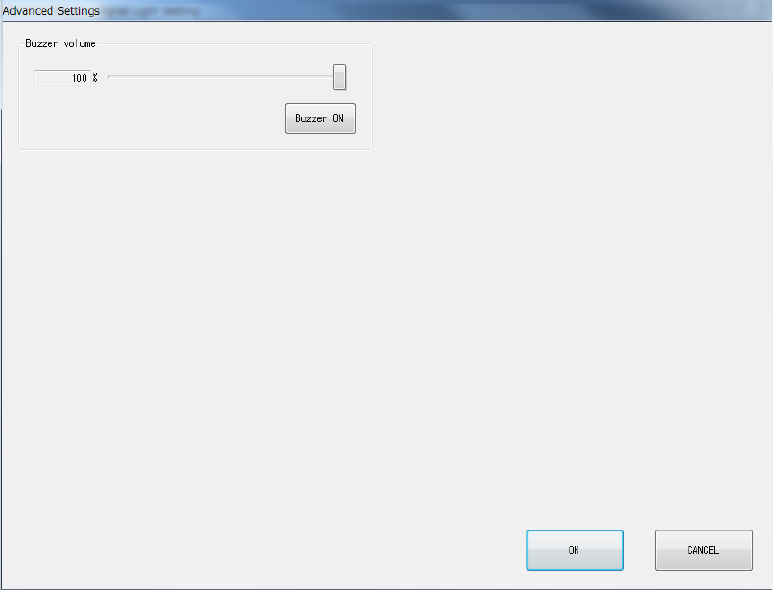
8.3.6.1.1 Advanced Settings
When you click <Advanced Settings> on the Signal Light Setting screen, the screen shown below
will appear.
(1) Buzzer volume
You can set the buzzer sounding volume by moving the slider.
When you click the <Buzzer ON> button, the buzzer sounds using the set volume. Clicking
this button again will stop the buzzer sound.
Part 2 Detailed Description of Each Function Chapter 8 Machine Setup
8-48
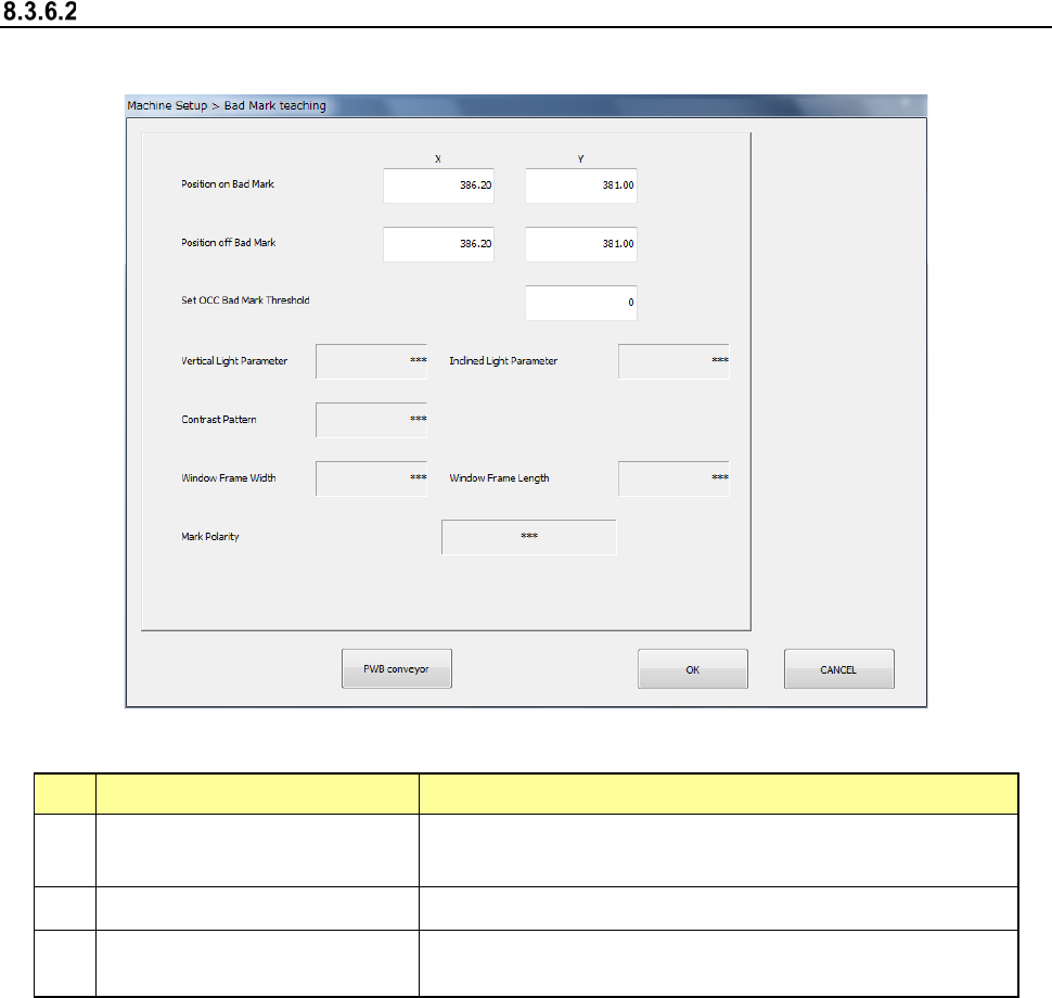
Bad mark teaching
When you select [Bad mark teaching], the following screen appears.
(1) Setting items
No. Item Description
1
Position with a mark
X-coordinates/Y-
coordinates of the center position of the bad
mark
2
Position without any mark
Position without any bad mark (top surface of the board)
3
OCC bad mark threshold value
setting
Threshold value when recognizing a bad mark by camera
(2) How to set
1) Enter each value from the software keyboard
2) Enter each value by using the “Teaching” function displayed in the Operation area.
3) For XY position, values are fetched and incorporated simultaneously regardless of the
input focus position.
4) Put a focus onto the OCC bad mark threshold value setting and execute teaching by
pressing “Teaching” of the operation area.
(3) Executing operation (OCC)
1) Put a focus onto the OCC bad mark threshold value setting and execute teaching by
pressing “Teaching” of the operation area.