RS-1_instruction manual.pdf - 第218页
Part 1 B asic O peration Chapter 2 Pr oduction 2- 107 Placement trac king Overview When you se lect the [P lacement tr acking] comm and from the “Suppor t” menu invoked f rom the “Product ” menu, the “ Placement tracking…
Part 1 Basic Operation Chapter 2 Production
2-106
(1) Checking to see if each VCS is stained or not
Item Description
Reject Level
Displays settings of the average value “Average Reject Level,” the maximum value
“Maximum Reject Level” and the standard deviation “Standard Deviation Reject Level.”
Reject Value
Displays the average value “Average Reject Level,” the maximum value “Maximum Reject
Level” and the standard deviation “Standard Deviation Reject Level” that are detected with
the check.
Status Displays the result if the corresponding VCS is stained.
See Section 11.3.3.3 “VCS Dirty Check” of Chapter 11 “Self-diagnosis Function” for details.
Verify All check
See Section 2.12.3 “Verify check (optional)” for details.
GNRL. Vision direction continuous inspection
See Section 2.12.4 “General vision component direction inspection” for details.
PWB Height
See Section "4-5-7-2 Measurement of mounting board surface height" in "Chapter 4 Program" for
details.
Part 1 Basic Operation Chapter 2 Production
2-107
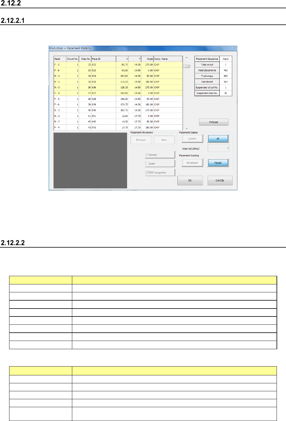
Placement tracking
Overview
When you select the [Placement tracking] command from the “Support” menu invoked from the
“Product” menu, the “Placement tracking” screen appears.
On this screen, the system displays the list of placement operations before start of PWB production,
and displays each component placement position in order to allow you to check whether a
component is placed on a board already or not.
Therefore, you can decide whether to place a component on a board to produce PWBs
continuously.
“Placement tracking” screen
(1) List of placement operations
The system displays information on placements in sequence order on the upper left section of
the screen.
Menu item
Description
Head
Displays the number of a head that is to be used to place a component.
Circuit No.
Displays the number of a circuit on which a component is placed.
Step No.
Displays the number a step for placing a component.
Place ID
Displays the ID of a component to be placed.
X
Displays an X coordinate at which a component is to be placed.
Y
Displays a Y coordinate at which a component is to be placed.
Angle
Displays the angle of a component that is to be placed.
Comp. Name
Displays the name of a component that is to be placed.
(2) List of total placement information (“Production Information”)
The system displays the general component placement information.
Menu item
Description
Placement Sequence
Displays whether the placement sequence is in input order or optimized order.
Total circuit
Displays the total number of circuits that are to be placed on a board.
Total placements
Displays the total number of component placement positions on a board.
Total steps
Displays the number of components placed on a board with the selected station.
Not placed
Displays the number of component placement positions at which any component is
not placed yet with the selected station.
Part 1 Basic Operation Chapter 2 Production
2-108
Suspended circuit No.
Displays the number of a circuit on which a component placement is aborted with the
selected station.
Suspended step No.
Displays the number of a step in which a component placement is aborted with the
selected station.
(3) PWB set
Clamps a board of which the placement positions are to be checked.
Menu item Description
PWB set Loads a board/re-clamps a board.
(4) Placement Display
Placement operation displayed on the list above is superimposed on the screen.
Menu item
Description
Current
When you press the <START> switch, the selected component placement position is
displayed.
All
When you press the <START> switch, the system starts displaying component
placement positions from the selected one.
When you press the <STOP> switch, the system stops displaying component
placement positions.
Interval (100ms)
Enter the time period when the system has to wait before it moves to the next
component placement positions in Continuous Tracking mode.
Always
This button always displays the component placement position that is being selected.
When you change the selected position, the system displays the changed component
placement position.
Zoom
This button allows you to select whether to zoom the displayed component
placement position or not.
BOC mark recognition
The system recognizes a BOC mark if necessary before displaying a component
placement position.
Area mark recognition
The system recognizes an area mark if necessary before displaying a component
placement position.
(5) Placement Movement
You can select a component placement position from the list.
Menu item
Description
Previous
Selects the component placement position immediately before the selected one.
If the selected position is the first position, this button does not function.
Next
Selects the component placement position immediately after the selected one.
If the selected position is the last position, this button does not function.
(6) Placement tracking
Set a component placement position selected on the list as a position on which a component is
already placed or not.
Menu item
Description
Not placed
Any component is not placed on the selected placement position.
The system will place a component there with continuous production.
Placed
A component is placed on the selected placement position.
The system will not place any component there with continuous production.
(7) Superimpose
The system will superimpose the selected component placement position on the screen.