RS-1_instruction manual.pdf - 第155页
Part 1 B asic O peration Chapter 2 Pr oduction 2- 44 4) Items for r ecognition of m arks This item d isplays the m ark recogn i tion scr een. When the syst em recogn izes a mark, it displ ays the superim pose screen over…
Part 1 Basic Operation Chapter 2 Production
2-43
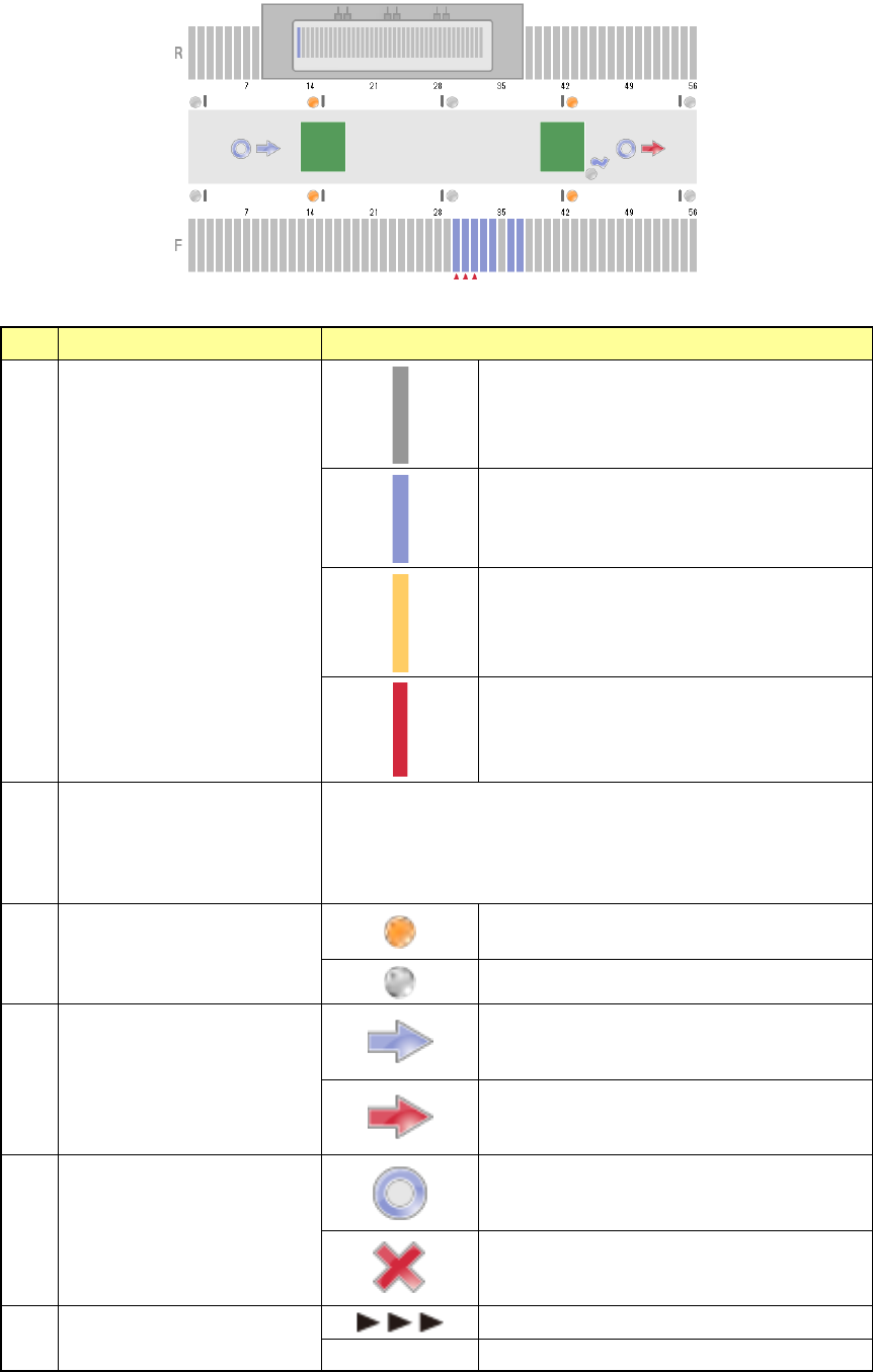
3) Items for bank/conveyor information
The state of the banks and that of the conveyor are shown here.
Information shown with each item is as follows.
No.
Item
Description
1 Feeder state
No feeder
Normal state
Components run out.
Error state
2 Worst feeder
Worst 3 feeders
Set the worst feeder with the menu item “Worst feeder selection
method” on the “Production (Display)” tab invoked from the
“Operation option” screen.
(“Pick-up rate” or “Number of pick-up errors”)
3
In sensor, WAIT sensor,
WAIT2 sensor, Stop sensor,
C-Out sensor, Out sensor
The sensor is set to ON.
The sensor is set to OFF.
4 Ready signal
The sensor is set to OFF.
The sensor is set to ON.
5 Board available
The sensor is set to OFF.
The sensor is set to ON.
6 Conveyor motor state
The motor is operating.
No display The motor is stopping.
Part 1 Basic Operation Chapter 2 Production
2-44
4) Items for recognition of marks
This item displays the mark recognition screen.
When the system recognizes a mark, it displays the superimpose screen over the stop sensor
of the conveyor information.
No.
Type
1
BOC mark
2
Area mark
3
Bad mark
4
Bank mark
5
Area bad mark
6
Global bad mark
Vision
When you select the commands, [Window] and [Production status (Vision)], the “Production status
(Vision)” screen appears.
Each mark whose image is taken during production and the superimpose screen are displayed. The
figure below shows the example of displaying the screen.
1) Item for production state
The production state on the currently superimposed screen is displayed.
The following production states are displayed on the “Production status (Vision)” screen.
No.
Display
State
1
Recognizing component with
VCS
Recognizing vision recognition components with
VCS
2 Multi recognizing
The process for multi-recognizing a component that
is to be multi-recognized is being performed.
3
SVCS recognizing
The process for using a SVCS to recognize a component
that is to be recognized with a SVCS is being performed.
4
Recognizing area mark
Recognizing an area mark
5
Recognizing BOC mark
Recognizing a BOC mark
6
Recognizing bad mark
Detecting a bad mark with the OCC
7
Recognizing bank mark
Recognizing a bank mark
8
Recognizing area bad mark
Recognizing an area bad mark
9
Recognizing global bad mark
Detecting a global bad mark with the OCC
10
Other states
Cal mark recognition, Nozzle D-cut detection
Part 1 Basic Operation Chapter 2 Production
2-45
2) Items for production information
The general information on PWB production is displayed here.
No.
Item
Description
1 No. of PWBs
Shows “the number of PWBs produced already / the number of
PWBs planned to be produced.”
When the item “Count down the number of boards produced” is
selected on the Production (Display) tab of the “Operation option”
menu, this field shows “the number of PWBs that will be produced
from now / the number of PWBs planned to be produced.”
2
Total Pl
Shows the total number of components to be placed on boards.
3 Sequence
Shows the component placement sequence, Input order or
Optimized order.
4 Line Tact time
Sows the time passed from when one board was ejected from the
machine until when the next board was ejected.
5 Mach. Tact time
Shows the time passed from when one board was loaded to the
machine until when the board was ejected from the machine.
6
Total Pl. rate (%)
Shows the total component placement rate of the machine.
7
Total pick rate (%)
Shows the total component pick-up rate of the machine.
8
Cmp. run out
Shows the accumulated number of times components run out.
9 Laser Error
Shows the accumulated number of times a laser recognition error
occurred.
10 Cmp. Remove
Shows the accumulated number of times a picked-up component
was discarded.
3) Items for production operation
Following are the items that display the production operation on the currently superimposed
screen.
No.
Item
Description
1 Head
Shows a number of a head unit indicated in an item.
Shows either L or R when bank mark is recognized; shows the unit
used for recognition when any other mark is recognized.
2 Circuit No.
Shows a number of a circuit of components that are picked and
placed by head unit.
3 Step No.
Shows a number of placement data of components that are picked
by a head unit and a number of a mark when BOC mark or bank
mark is recognized by a head unit.
4
Total Pl.
Shows the number of components that are placed on PWB.
5 Pick Pos.
Shows the feeder position where components are picked by a head
unit
6
Nozzle No.
Shows the number of nozzles that are held by a head unit
7
Cmp Name
Shows the names of components that are picked by a head unit
8 Cmp. ID
Shows the placement IDs of components that are picked by a head
unit