RS-1_instruction manual.pdf - 第810页
Part 2 D etaile d Descript ion of E ach Functi on Chapter 9 M anual Control 9- 38 9.6.7 Component verification When you se lect the [CV S control] command from the “ Other ” menu, the dia l og box for indicati ng the ser…
Part 2 Detailed Description of Each Function Chapter 9 Manual Control
9-37
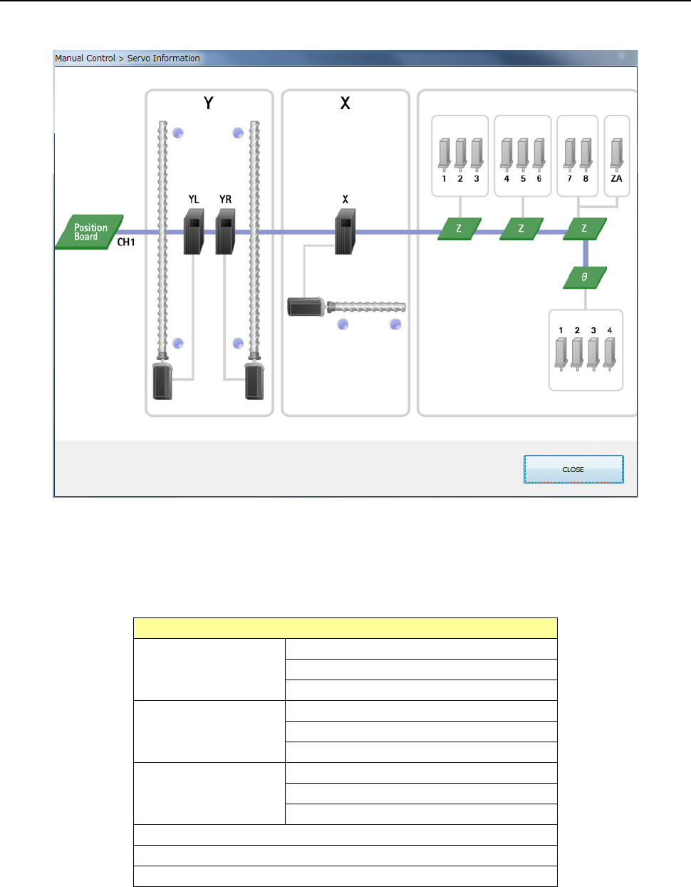
9.6.6 Servo status
When you select [Other] - [Servo status] in the menu, the servo status dialog appears.
(1) Servo statusThe current condition of each servo is displayed here.
A unit at which a servo error occurs is displayed in red.
When you move the cursor over a unit icon or each sensor icon, the corresponding tool hint
appears on the screen.
Unit
Y axis right
Amplifier
Motor
Limit sensor plus/minus
Y axis left
Amplifier
Motor
Limit sensor plus/minus
X axis
Amplifier
Motor
Limit sensor plus/minus
Theta 1 to Theta 4
Z1 to Z8, ZA
Position board
Part 2 Detailed Description of Each Function Chapter 9 Manual Control
9-38
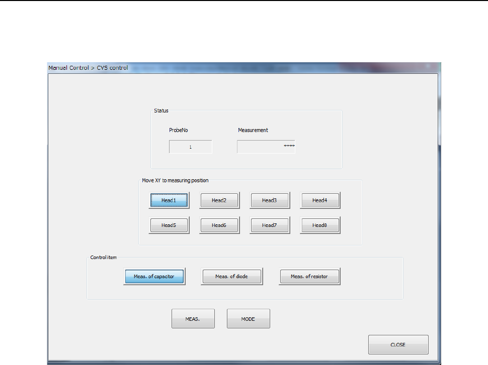
9.6.7 Component verification
When you select the [CVS control] command from the “Other” menu, the dialog box for indicating
the servo condition appears on the screen.
This dialog box is displayed only when the machine is equipped with a CVS option.
(1) Status
The measurement result is displayed here after measurement finishes.
(2) Move XY to measuring position
The head specified with one of these buttons is moved in the XY direction.
(3) Control item
Select the desired control item with the corresponding radio button.
1) Meas. Capacitor
The capacity of a capacitor component is measured. Press the [MEAS.] button and
the [MODE] button for control.
2) Meas. of diode
The polarity of a diode component is measured. Press the [MEAS.] button and the
[MODE] button for control.
3) Meas. of resistor
The resistance value of the resistor component is measured. Press the [MEAS.]
button and the [MODE] button for control.
Part 2 Detailed Description of Each Function Chapter 9 Manual Control
9-39
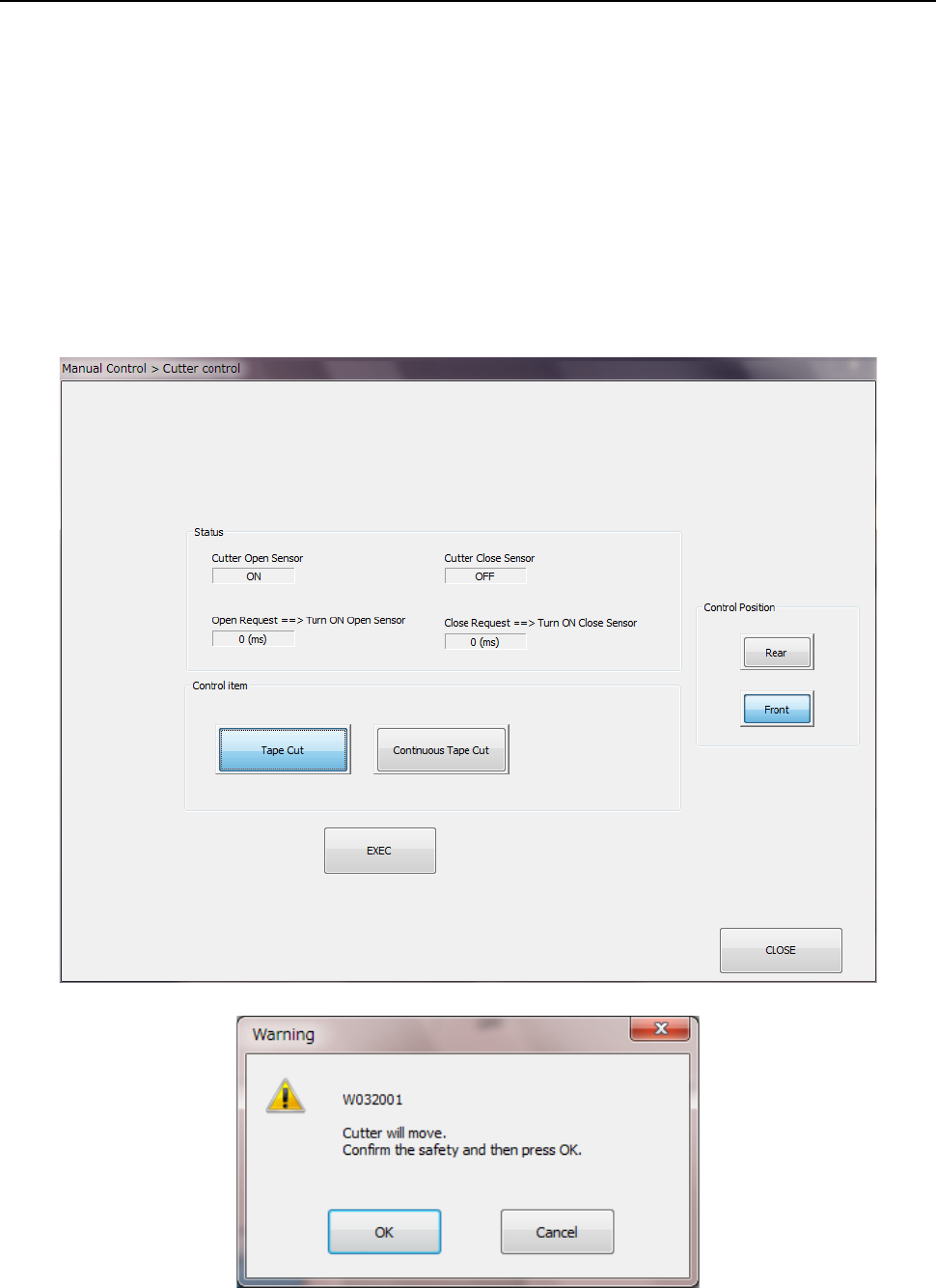
9.6.8 Cutter control
When you select [Other] – [Cutter control] in the menu, the cutter control dialog appears. Select
an operation by the radio button (“Tape cut” or “Continuous tape cut”) of the control item and press
the <EXEC> button. When you press the <EXEC> button, the inquiry dialog is displayed. Them,
press the <OK> button to start the operation.
The sensor status of the cutter unit and the sensor reaction time are displayed in the status
display.
To stop the continuous tape cut operation, press the <Stop> button.
Any cutter operation cannot be performed under the following conditions:
- When the cover of the main unit opens,
- When the main unit is stopping in emergency situations and/or
- When the MTS is stopping in emergency situations.