RS-1_instruction manual.pdf - 第442页
Part 1 B asic O peration Chapter 4 Cr eating a Produc tion Progra m 4- 107 The “V ision 2” tab allows you t o set informat ion on leads. Menu item Overvie w Length Enter the lengt h of a sect ion of a lead t hat is in co…
Part 1 Basic Operation Chapter 4 Creating a Production Program
4-106
The “Vision 2” tab allows you to set information on leads.
Menu item
Overview
Length
Enter the length of a section of a lead that is in contact with a board.
Width
Enter the width of a lead.
Count
Enter the number of leads when a component type is a lead component.
Start 1 to 3
Enter the position of a missing lead.
The input range is from 0 to the number of leads (default: 0).
Miss 1 to 3
Enter the number of missing leads.
The input range is from 0 to the number of leads (default: 0).
10) Bidirectional lead, Z-lead
The “Vision 1” tab allows you to set a lead pitch and a lead bending level.
Menu item
Overview
Lead Pitch
Enter the distance between two consecutive leads.
Bend level
Select the bending level of a lead to be detected among “15 %,” “20 %,” “25 %,”
“30 %” and “None.”
The default value is 20 %.
View Field
Select the range of leads of a connector component to be recognized and that not to
be recognized among “All” (all leads), “Only the both ends lead” (only leads on both
ends) and “Both ends lead exclusion” (leads on both ends are excluded).
“All” is selected by default.
When you select “Only the both ends lead” or “Both ends lead exclusion,” the items
“L Top,” “R Top,” “L Bot.” and “R Bot.” are displayed.
Part 1 Basic Operation Chapter 4 Creating a Production Program
4-107
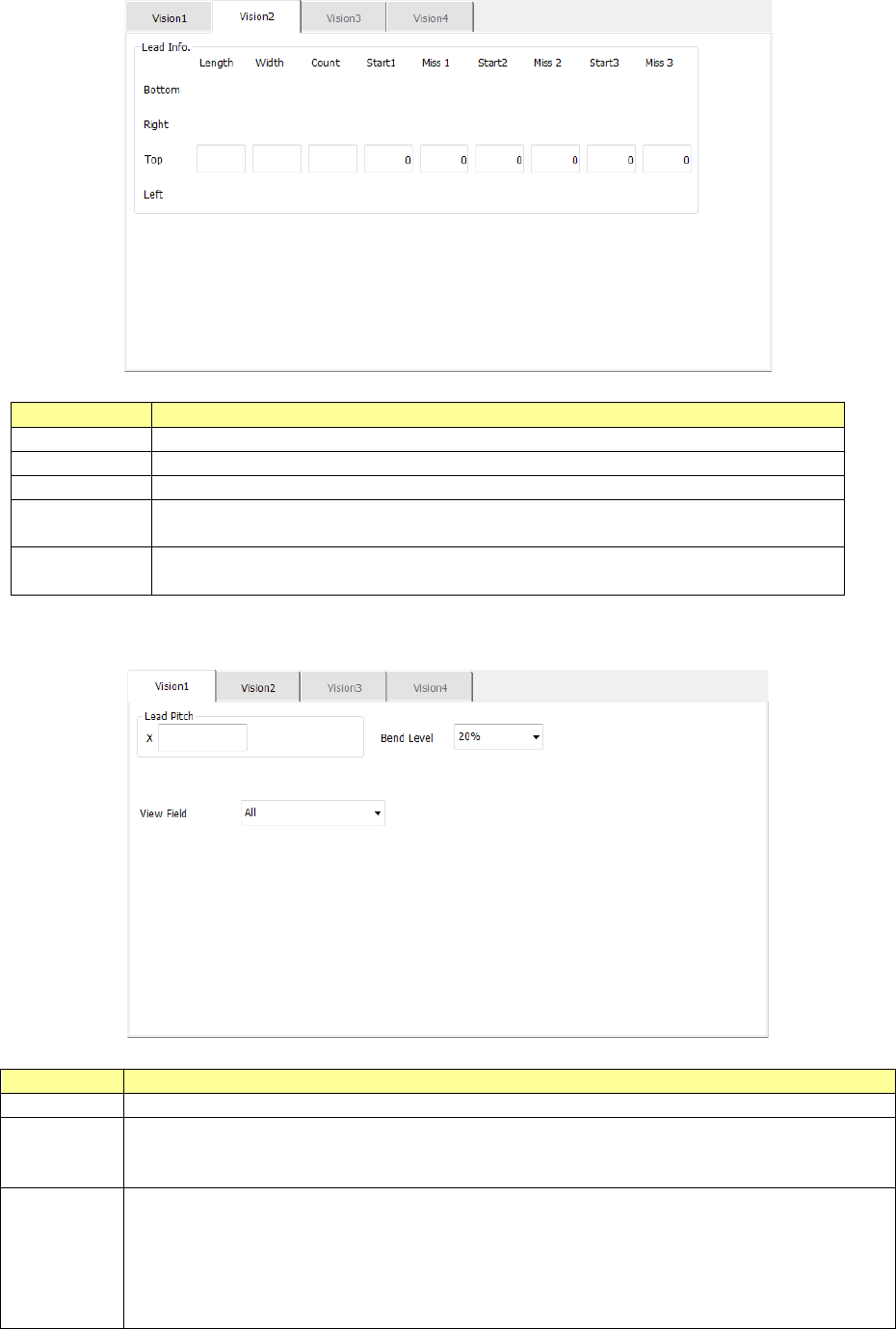
The “Vision 2” tab allows you to set information on leads.
Menu item
Overview
Length
Enter the length of a section of a lead that is in contact with a board.
Width
Enter the width of a lead.
Count
Enter the number of leads when a component type is a lead component.
Start 1 to 3
Enter the position of a missing lead.
The input range is from 0 to the number of leads (default: 0).
Miss 1 to 3
Enter the number of missing leads.
The input range is from 0 to the number of leads (default: 0).
11) GaAsFET
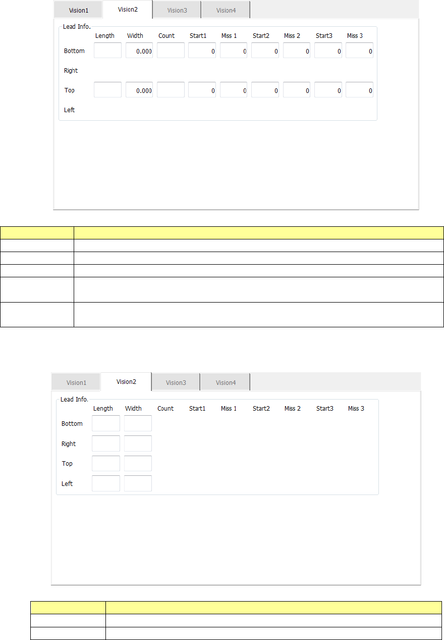
The “Vision 2” tab allows you to set information on leads only.
Menu item
Overview
Length
Enter the length of a section of a lead that is in contact with a board.
Width
Enter the width of a lead.
Part 1 Basic Operation Chapter 4 Creating a Production Program
4-108
12) Aluminum electrolytic capacitor
The “Vision 2” tab allows you to set information on leads only.
Menu item
Overview
Length
Enter the length of a section of a lead that is in contact with a board.
Width
Enter the width of a lead.
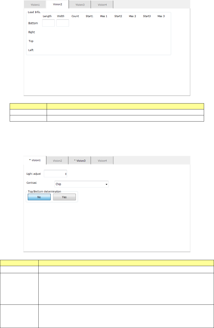
13) Square chip and outline-recognized component
Specify the brightness correction with the menu item “Light adjust,” the recognition type with
the menu item “Contrast” and whether to determine the side, the top or the bottom with the
menu item “Top/Bottom detection.”
Menu item
Overview
Light adjust
Enter the correction value for the contrast when a component is irradiated.
Contrast
Select one of the following recognition patterns from the combo box: “4
sides,” “4 corners”, “Square chip” and “Center.”
“4 sides” is selected by default.
Note that you can select only “Chip” (square chip) here when the component
type is “Chip.”
Top/Bottom
determination
Only when the component type is “Chip” (square chip), select whether to
determine the side of a component, the top or the bottom.
When you select the <Yes> button, the “Vision 4” tab is enabled, and you can
make the detailed settings for determining the side, the top or the bottom.