RS-1_instruction manual.pdf - 第48页
Part 1 B asic O peration Chapter 1 Overv iew of the Machine 1- 30 X, Y, Z , Z A, a nd θ a xes d escriptions The follow ing four axes ( X, Y , Z, and θ ) are numerically contro lled in this mac hine. (1) X- and Y -axis Th…
Part 1 Basic Operation Chapter 1 Overview of the Machine
1-29
Others
(1) Automatic tool changer (ATC)
The ATC can accommodate up to 45 nozzles.
When a large-sized nozzle is supported, the ATC can accommodate up to 38 nozzles.
(2) Transport rail height
900 mm ± 20 mm (For Japan, China and southeastern Asian countries models)
950 mm ± 20 mm (For the U.S.A. and Europe models)
(3) Air requirements
Air pressure: 0.5 ± 0.05 Mpa
Maximum air consumption: Vacuum pump 50 L/minute (standard condition), Ejector 200
L/min (standard condition)
Dry air: Dew point under pressure 10 °C or less (Oil and dust shall be
removed appropriately.)
* The following organic solvents and chemicals will deteriorate the polycarbonate resin of the
air combination case unit. Do not use them.
Type
Chemical name
Acid:
Hydrochloric acid, phosphoric acid sulfate, chromic acid
Alkali:
Caustic soda, caustic potash, slaked lime, ammonia water, sodium carbonate
Inorganic salt:
Soda sulfide, potassium nitrate, soda nitrate
Chlorine solvent:
Carbon tetrachloride, chloroform, ethylene chloride, methylene chloride
Aromatic type:
Benzene, cyclohexane, thinner
Ketone type:
Acetone, methyl ethyl ketone, cyclohexane
Alcohol type:
Ethyl alcohol, IPA, methyl alcohol
Oil type:
Gasoline, kerosene, water-soluble cutting oil (alkaline)
Ester type:
Dimethyl phthalate, diethyl phthalate
Ether type:
Methyl ether, ethyl ether
Amine:
Methyl amine
Others:
Screw lock liquid, salt water, leak taster
(4) Noise level: 73 dB (A) or less
(5) Country of manufacturing: Manufactured in Japan
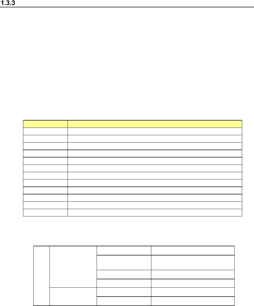
(6) Environmental conditions
Environment requirements
During operation
Temperature 10℃ to 35℃
Accuracy guaranty
temperature
22℃ to 25℃
Humidity
50%RH or less (35℃)
Altitude 1000m or less
Transportation or
storage
Temperature -15℃ to 70℃
Humidity 20 to 95%RH (No condensation)
(7) Installation conditions
Overvoltage Category: Category III (IEC60664-1)
Pollution Degree: Degree 3 (IEC60664-1)
Part 1 Basic Operation Chapter 1 Overview of the Machine
1-30
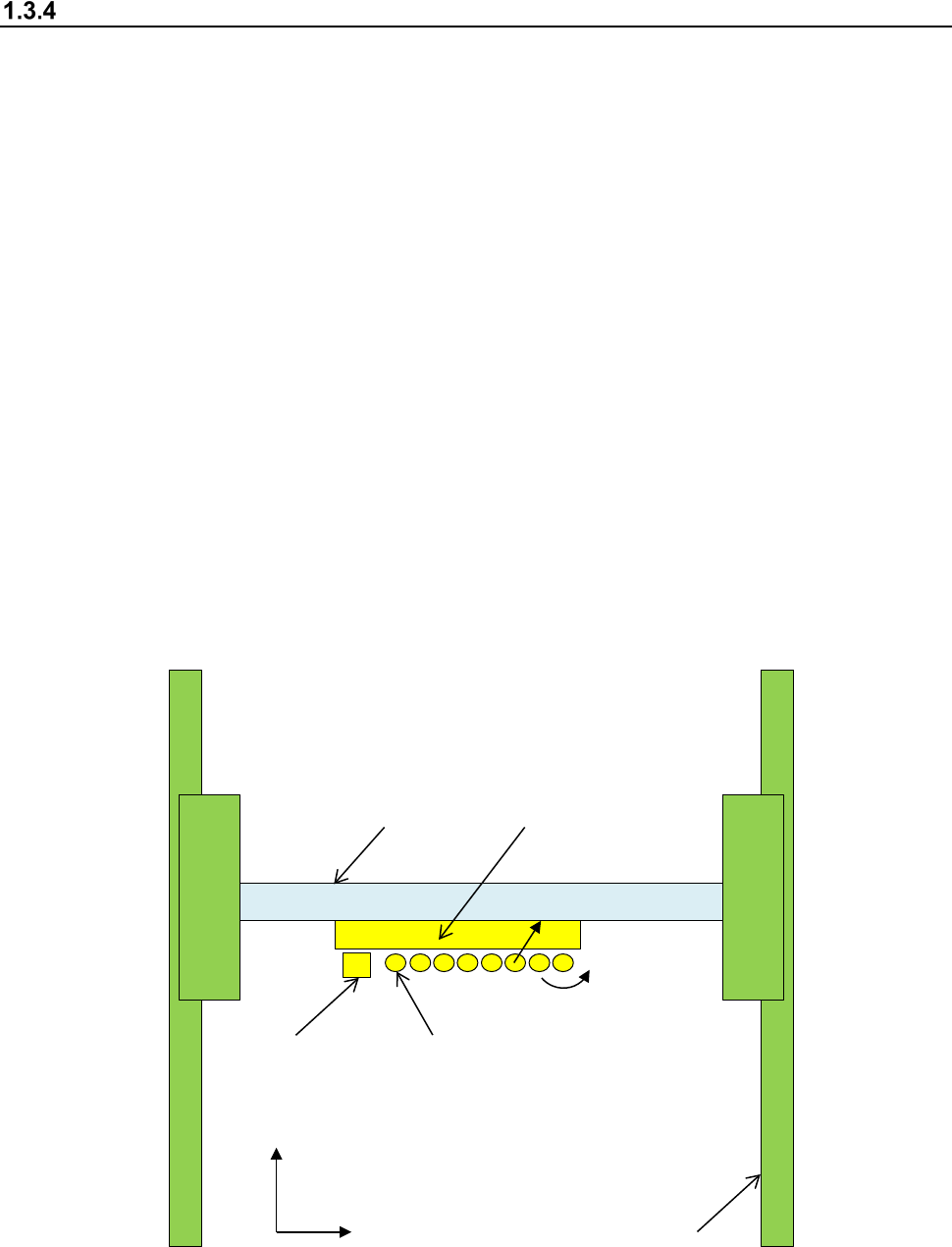
X, Y, Z, ZA, and θ axes descriptions
The following four axes (X, Y, Z, and θ) are numerically controlled in this machine.
(1) X- and Y-axis
The X-axis represents the left and right directions of the machine, while the Y-axis represents
the front and rear directions: a position is given as X = xxx.xx mm and Y = xxx.xx mm in
increments of 0.01 mm. Two coordinate systems are available:
one given by the production program and another given by teaching operation.
Both coordinate systems are automatically changed, so you do not have to switch
the coordinate system by yourself.
(2) Z-axis
The Z-axis represents the height direction of a nozzle, given as Z = xx.xx mm, in 0.01-mm
increments.
The upward direction is positive (+), with the top side of a board clamped (any jig is not used)
being 0.
(3) θ-axis
The q-axis represents the rotation angle of the head, given as "A = xx.xx" (in 0.05 increments.)
The value is positive for counterclockwise rotation and negative for clockwise rotation.
(4) ZA-axis
The ZA-axis represents the height direction of the LNC120 sensor, given as Z = xx.xx mm, in
0.01-mm increments.
The upward direction is positive (+), with the top side of a board clamped (any jig is not used)
being 0.
X-axis
Y-axis
Head
Y+
X+
Z+
θ
+
OCC
L1 nozzle shaft
L1 to L8 from left to right
Part 1 Basic Operation Chapter 1 Overview of the Machine
1-31
Electrical specifications
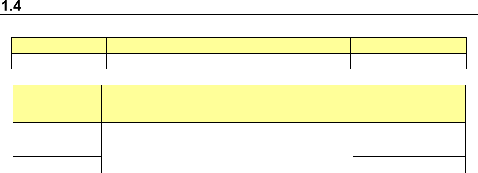
(1) Control Systems
Item
Control system
Resolution
X-Y Semi-closed-loop control system with the AC serve motor 0.0001 mm
Models Control system Resolution
Z
Semi-closed-loop control system with the AC serve motor
0.0305 μm
θ
0.00137°
ZA 0.0299 μm
(2) Main CPU
Intel® Celeron
(3) Display
Support of a 15-inch touch panel (SVGA mode LCD panel)
(4) Data and program input/output
You can manually enter data with the software ten-key of a touch panel.
By using USB flash memory, you can transfer data such as production program.
When this is connected to Floor productivity improvement support system, data communication
can be performed by LAN interface.
(5) USB port
External drives or external storage devices can be connected via the USB port.
(6) Power requirements
Voltage (three-phase) : 200 V AC (standard)
: 220 V, 240 V, 380 V, 400 V, 415 V AC (option)
Allowable voltage range : ± 10 % (for the rated voltage)
Apparent power : 2.2 kVA
Frequency : 50/60 Hz
Size of the primary-side power cable : 5.5 mm
2
or more
Size of the protective grounding lead wire : 5.5 mm
2
or more
(7) Protection at power failure (Uninterruptible power-supply system)
This machine is equipped with the ATX power supply working as uninterruptible power supply to
prevent data from being damaged or lost due to power failure.
Batteries are used as the back-up power supply of the ATX power supply, so the ATX power
supply is designed to stop the system before these batteries run down. Therefore, even during
power failure, the system can be terminated safely so that any data cannot be damaged or lost
even when a power failure occurs.