RS-1_instruction manual.pdf - 第176页
Part 1 B asic O peration Chapter 2 Pr oduction 2- 65 2.11 Produc tion Program When the stocke d components run out Overview When you selec t the [Pro gram] comm and from the “Product ” men u, and then the [Comp onent sup…
Part 1 Basic Operation Chapter 2 Production
2-64
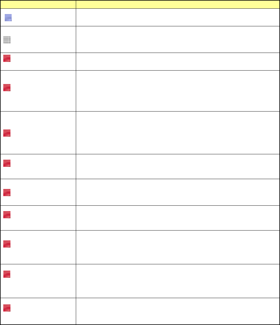
<Error Details>
Error
Contents
No display
The electric feeder is specified in the production program and the electric feeder is
correctly mounted on the electric feeder bank.
Unloaded
This error is shown if the electric feeder is specified in the production program, but
the electric feeder is not mounted on the electric feeder bank.
Mount the electric feeder on the electric feeder bank.
Electric feeder bank is
not connected.
This error is shown if the electric feeder is specified in the production program, but
the electric feeder bank is not connected. Mount the electric feeder bank.
Feeder type is
different.
This error is shown if the electric feeder is specified in the production program, but
an electric feeder with a different feeder type is mounted on the electric feeder
bank.
The currently mounted electric feeder type is also shown.
Mount an electric feeder with the feeder type meeting the production program.
Tape pitch is different.
This error is shown if the electric feeder is specified in the production program, but
an electric feeder with a different tape pitch is mounted on the electric feeder bank.
The component tape pitch (PRG:xxx) specified in the production program and the
tape pitch (ETF:xxx) of the currently mounted electric feeder are also shown.
Mount an electric feeder with the tape pitch meeting the production program.
Panel switch is being
operated.
This error is shown if the electric feeder is specified in the production program and
the electric feeder mounted on the electric feeder bank is operated with the panel
switch. Finish the operation of the operation switch.
Tension error
This error is shown if the electric feeder is specified in the production program and
the tension error occurs in the electric feeder mounted on the electric feeder bank.
Adjust the tension of the electric feeder.
Power voltage drop
error
This error is shown if the electric feeder is specified in the production program and
the power voltage drop error occurs in the electric feeder mounted on the electric
feeder bank. Adjust the power voltage of the electric feeder.
Feeder origin return is
not completed.
This error is shown if the electric feeder is specified in the production program and
the origin return of the electric feeder mounted on the electric feeder bank is not
completed.
Perform the origin return of the electric feeder.
Loss of
synchronization occurs
in the feeder.
This error is shown if the electric feeder is specified in the production program and
loss of synchronization occurs in the electric feeder mounted on the electric feeder
bank.
Reset the electric feeder, and return it to the origin.
Feeder is returning to
its origin.
This error is shown if the electric feeder is specified in the production program and
the electric feeder mounted on the electric feeder bank performs the origin return.
Wait until the origin return operation of the electric feeder is completed.
Part 1 Basic Operation Chapter 2 Production
2-65
2.11 Production Program
When the stocked components run out
Overview
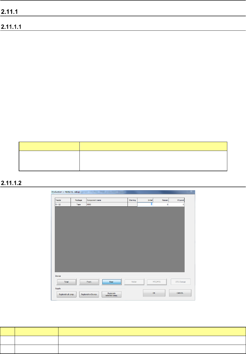
When you select the [Program] command from the “Product” menu, and then the [Component supply]
command on the “Program” menu, the “Parts no. setup” screen appears.
Enter the number of components for controlling the number of the remaining components on this screen.
If you do not enter any value, “0” is set to a feeder.
In this case, the system does not control the number of the remaining components located on the feeder.
After setting components on a component supply unit (feeder, holder, DTS, MTC or MTS) specified on
the “Pick” data screen, set the number of components to the main unit.
If a pick-up retry over error occurs at a a component supply unit (feeder, holder, DTS, MTC or MTS), the
system judges that components run out at the feeder and skips the corresponding pick-up operation to
continue the current production.
In order to continue the current PWB production with using again the component supply unit on which an
error occurred, you have to clear the error after adjusting the feeder so that the machine can pick up a
component from it.
Perform this error clear operation on this “Parts no. setup” screen also.
In the following case, the main unit flashes the yellow signal light to warn the operator.
(This operation is performed when you use the JUKI standard settings. See Section 8.3.6.1 “Signal
light” of Chapter 8 “Machine Setup” also.)
Component supply unit Condition the yellow signal light flashes
Tape feeder
Stick feeder
- When the number of the remaining components set on each feeder
is below the number set as the warning level, or
- When a component pick-up retry over error occurs at a feeder.
Displayed screen
(1) List of the menu items
The menu items of the number of components on each component supply unit are shown here.
1) Items displayed when the [Parts no. setup] command is called
No. Item Description
1 Feeder Shows where to supply with components.
2 Package Shows the packaging style of a component (tape, stick and tray)
Part 1 Basic Operation Chapter 2 Production
2-66
3 Component name Shows the component name.
4 Warning
Shows the component supply error.
*: Indicates that the number of remaining components becomes less than the number
specified at “W.Level.”
E: Indicates that a component pick-up retry over error occurs, and the system stops
picking up a component.
To recover the system from an error: Enter the number of the remaining components
or replenish the feeder with components fully.
2) Items to be set
No.
Item
Description
1 Initial
Enter the number of components supplied in the package specified with “Package” before the system
starts using it. When you enter or change the initial value, the changed value is copied to the field of
the item “Remain.”
When you enter the initial value, the corresponding value is set in the “Remain” field.
- When you set “0”as this “Initial” value for a feeder, the system does not control the number of the
remaining components by subtracting the number of used components from this value and
continues producing PWBs until a retry over error occurs at the feeder. Otherwise, the value you set
here is entered to the field of the item “Remain” when you click the <Replenish Comp.> button.
2 Remain
- Shows the number of remaining components when the system checks the number of components.
This value decrements every time the system picks up a component during production.
- When “0” is set to “Initial,” the value shown here does not decrement.
- If you change the value of “Initial,” the value shown here is changed in the same manner. You can
also change this value only according to components to be supplied.
- When a tape feeder, stick feeder is used as a component supply unit, the system stops subtracting
the number of used components from the “Initial” value if this value reaches “0,” but continues
producing PWBs. When “0” is set in this “Remain” field, the system does not stop producing
PWBs either. In these cases, the feeder continues placing components on boards until a retry
over error occurs.
- The number of the remaining components becomes a smaller number than the value set in the
“Level” field, the signal light warns an operator.
3 W.Level
Sets the warning level.
When the number of remaining components becomes less than the value displayed here, the signal
tower warns you by flashing its yellow lamp.
If “0” is set to “Initial,” this function does not operate.
When you enter a value to “Initial,” this value is initialized.
(2) Device
No. Menu item Description
1
Tot al
Shows all components set on the machine.
2
Front
Shows only components set on the front bank.
3
Rear
Shows only components set on the rear bank.
4
Holder
Shows only components set on the holder or the DTS.
5
MTC/MTS
Shows only components set on the MTC or the MTS.
(3) DTS Change
When you press the <DTS Change> button, the system replaces a tray of the DTS with another
one. You cannot select this button if any DTS component is not specified in the production
program.
(4) Supply
When you press one of the < Supply> buttons, the system replenishes the specified component
supply unit with components fully.
When the system replenishes the unit with components, it resets the number of the remaining
components specified in the “Remain” field to the value specified in the “Initial” field, and
cancels the warning.
No.
Menu item
Description
1
Replenish all comp
Replenishes all types of components set on the machine fully.
2
Replenish Comp
Replenishes components whose type(s) is (are) displayed with the
<Device> button fully.