RS-1_instruction manual.pdf - 第40页
Part 1 B asic O peration Chapter 1 Overv iew of the Machine 1- 22 Mechanical specif ications Machine di mensions and mass (1) Machine dimensions Unit: mm Locati on Dimension Standard bo ard si ze Extra - large board si z…
Part 1 Basic Operation Chapter 1 Overview of the Machine
1-21
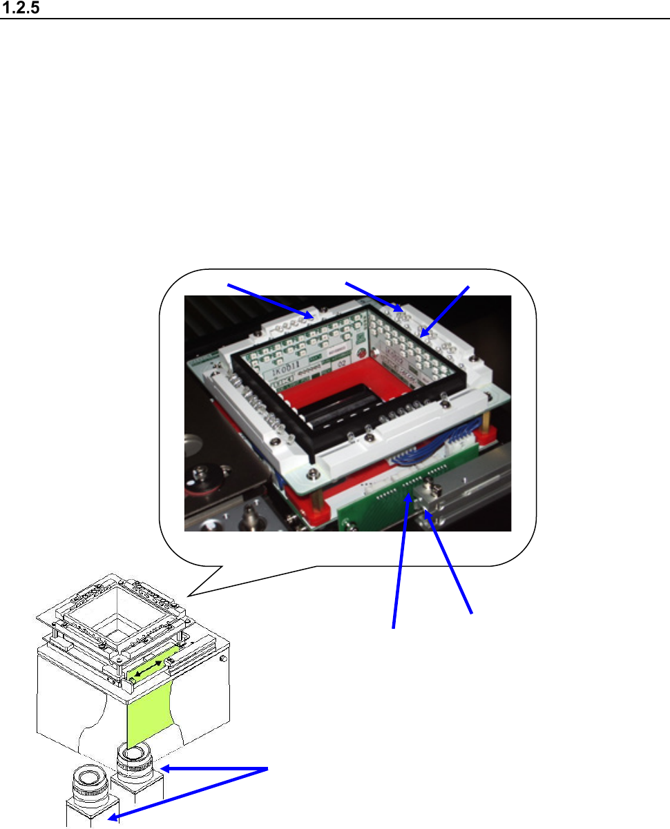
Configuration of a Vision Centering System (VCS)
When the combination and brightness of each LED lighting unit are adjusted, various lighting
patterns are generated and so a lighting pattern suitable for the object of recognition (lead, call, or
component outline) is generated.
The illuminated object of recognition is photographed by the VCS camera provided in the lower part
and then image processing is performed.
Reflective/coaxial lighting : Lead components such as QFP and SOP
Side lighting : Ball components such as BGA and CSP
Penetrative lighting : Outline recognition components
① LED board (for the upper transmittance light)
② LED board (for lower transmittance light)
③ LED board (for the side light)
④ LED board (for the coaxial light)
⑤ 54 mm/27mm/10mm view camera
⑥ Cylinder (Only added when setting 2 cameras)
⑤
③
①
②
④
⑥
Part 1 Basic Operation Chapter 1 Overview of the Machine
1-22
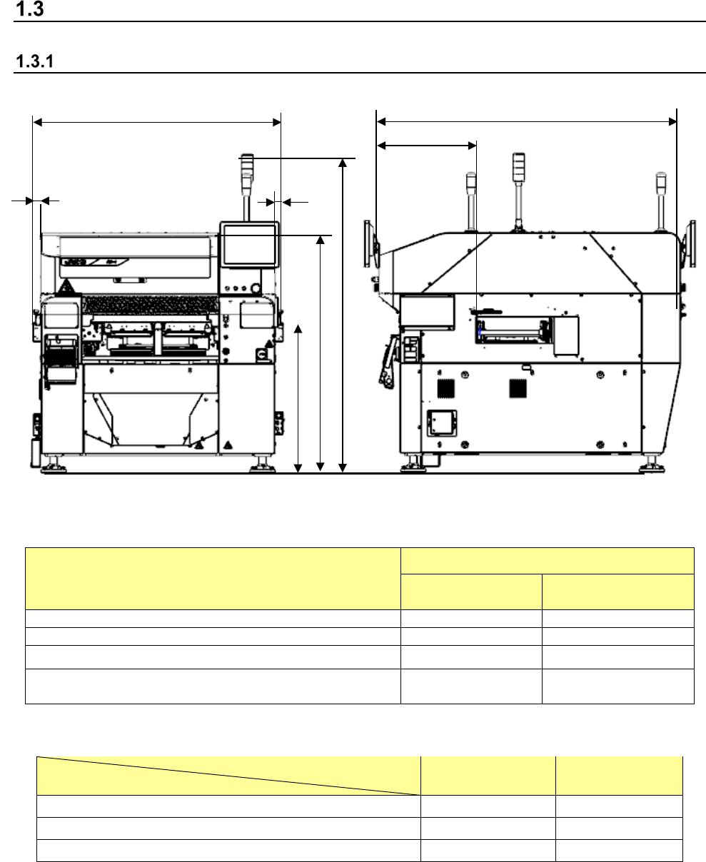
Mechanical specifications
Machine dimensions and mass
(1) Machine dimensions
Unit: mm
Location
Dimension
Standard board
size
Extra-large board
size
A (transport length)
1,500
2,109
C (depth: excluding LCD)
1,810
2,000
H (transport output amount) 50 Left: 354, Right: 220
I (Reference board transport path from the front of the
cover)
604 604
* The tolerance of the above dimensions shall be ±5 mm.
Unit: mm
Transport height
Dimensions
900mm 950mm
B (Top surface of the transport belt from the floor)
900
950
E (Top surface of the cover from the floor)
1,440
1,490
G (Top surface of the signal light from the floor)
1,905
1,955
(2) Mass
Standard board size: 1,700 Kg, Extra-large board size: 1,850 Kg
* Excluding bank and options.
A
B
E
G
H
H
C
I
Part 1 Basic Operation Chapter 1 Overview of the Machine
1-23
Placement accuracy
(1) Placement accuracy (X, Y)
The following table lists the placement accuracy data for different types of components.
A poorer accuracy than the value described below results depending on the components that
may have an edge or plastic mold burrs at the area detected with the laser align function, and
that may have a moving part to be detected with respect to the pick port.
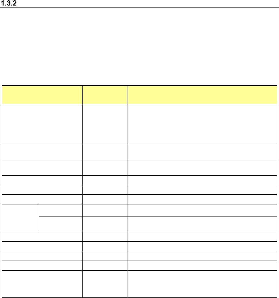
Component placement accuracy XY
(when a component is recognized with laser or board reference mark)
Unit: μm
Component type LNC120-8 Remarks
Square chip 03015, 0402
± 35
When the speed for moving down to place a component on a
board is set to “Slow 2”
Note: If a 03015 component cannot be recognized with laser
stably due to its shape (for example, if a string art image is not
displayed normally), use a VCS (10-mm field of view camera)
(optional).
Square chip 0603, 1005, 1608 or
more
± 50
Square chip (LED)
± 50
The placement accuracy of a square chip LED component shall
be attained when it can be recognized
MELF
± 100
SOT
± 150
See Note 2
Aluminum electrolytic capacitor
± 300
SOP, TSOP
Burr on one side
150 μm or less
± 150
See Note 3
In the direction
parallel to a lead
± 200
This accuracy shall be measured at the cross-section
measured with laser.
PLCC, DOJ
± 200
QFP,(Pitch: 0.8 or more)
± 100
See Note 3
QFP,(Pitch: 0.65)
± 50
See Note 3
BGA
± 100
Other large components
± 300
The accuracy obtained when the component placement
position is corrected according to the recognized component
image shall be an absolute value from a component reference
mark or a board reference mark.