RS-1_instruction manual.pdf - 第56页
Part 1 B asic O peration Chapter 1 Overv iew of the Machine 1- 38 (2) Comp onent hei ght The compo nent heig ht specificati ons of the RS -1 /1R differ fro m those o f the conv entional mac hin e. The height of t he plac…
Part 1 Basic Operation Chapter 1 Overview of the Machine
1-37
Note 4: Please refer to following, recognition component size of LNC120-8 unit.
* For the height restriction according to the component size, see "(2) Recognition height of laser
recognition component, and (3) Recognition height of image recognition component".
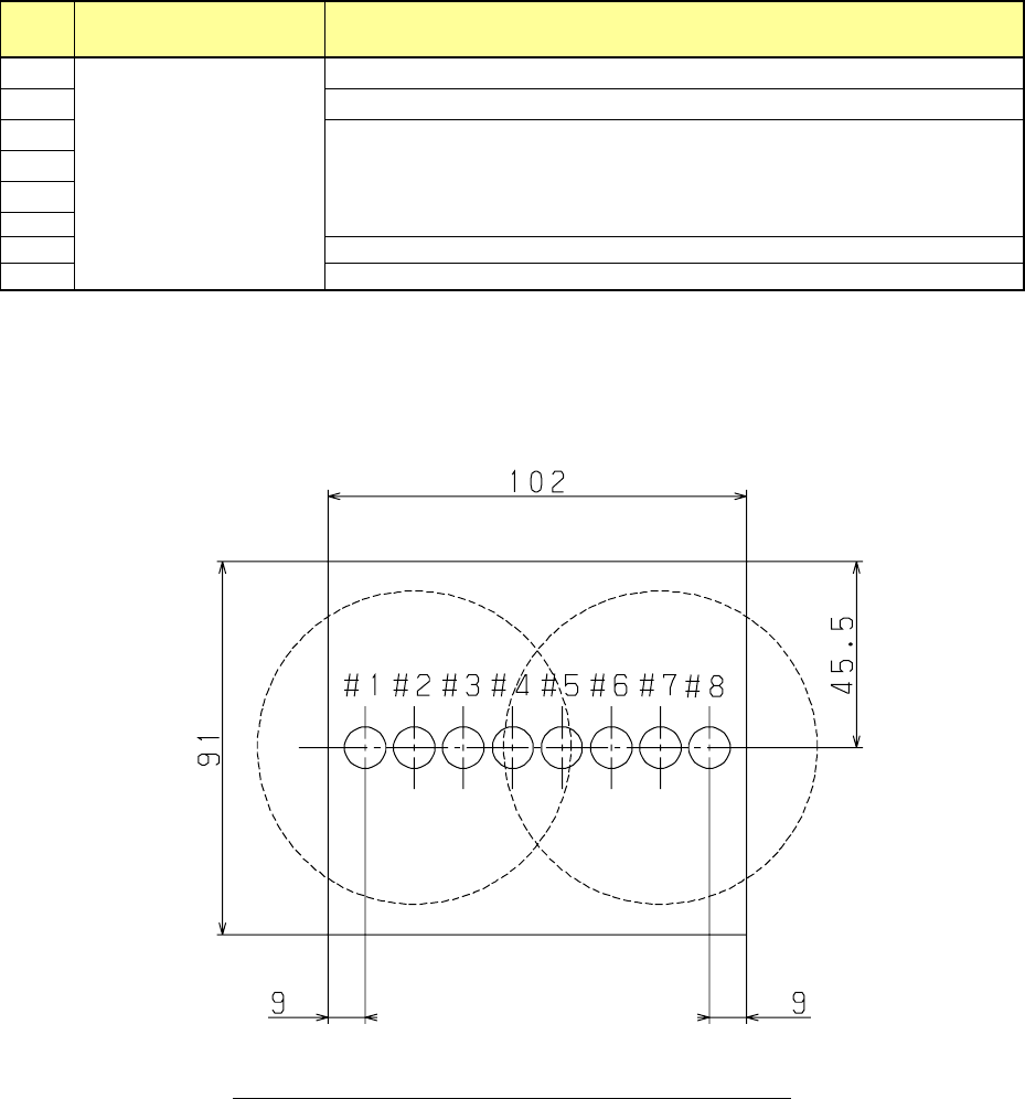
Nozzle
number
Simultaneous measurement
(Up to 8 nozzles)
Applicable maximum component size
1
03015 to □7mm
(Diagonal line length
9.90mm or less)
Up to
□20
mm or a component whose diagonal line length is up to 28.2 mm
2
Up to
□
35mm, or diagonal line 49.5mm
3
Up to □50mm, or diagonal line 70.7mm
4
5
6
7
Up to
□
35mm, or diagonal line 49.5mm
8
Up to
□20
mm or a component whose diagonal line length is up to 28.2 mm
* The maximum component aspect ratio that the LNC 120-8 unit can recognize is up to 60: 1.
* For simultaneous measurement of 4 axes at single axis interval, it is
□
14 mm or 19.8 mm diagonal.
* If a 03015 component cannot be recognized stably due to its shape (for example, if a string art image is
not displayed normally), use a VCS (10-mm field of view camera) (optional).
Fig. Position relations of LNC120-8 and the nozzle
Part 1 Basic Operation Chapter 1 Overview of the Machine
1-38
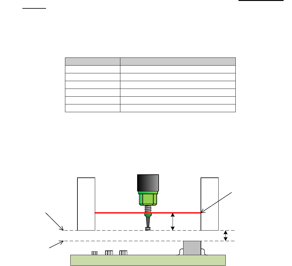
(2) Component height
The component height specifications of the RS-1/1R differ from those of the conventional
machine.
The height of the placeable component is changed by controlling the LNC120-8 unit position in
the Z-direction.
This shortens the distance between the pickup/placement position and LA surface and achieves
the improvement of the pickup-LA recognition-placement tact.
The position and movement axis of the LNC120 unit are determined to the ZA height and
ZA-axis, respectively.
The ZA height reference is the bottom surface of the LNC120-8 unit.
Additionally, the ZA height is not stepless and is set to several classes as shown below according
to the applicable component height.
Table ZA height classes
Class
Height of applicable component
1 [mm]
More than 0 [mm] and 1 [mm] or less
3 [mm]
3 [mm] or less
6 [mm]
6 [mm] or less
12 [mm]
12 [mm] or less
20 [mm]
20 [mm] or less
25 [mm]
25 [mm] or less
The XY-axis movable height has a margin of 3 [mm] in a class other than 1 [mm] class.
Components applicable to 1mm-class has a margin of 2 [mm].
Additionally, the distance between the bottom of the LNC120-8 unit and the LA surface is 5 [mm]
in each class.
2mmまたは3mm
LNC120下面高さ
XY軸移動可能高さ
搭載済み部品
の最大高さ
レーザ高さ
5mm
Fig. Margin of XY-axis movable height
Placed component
Max. height
Height of bottom surface
of LNC120-8
XY-axis movable height
2mm or 3mm
Laser height
Part 1 Basic Operation Chapter 1 Overview of the Machine
1-39
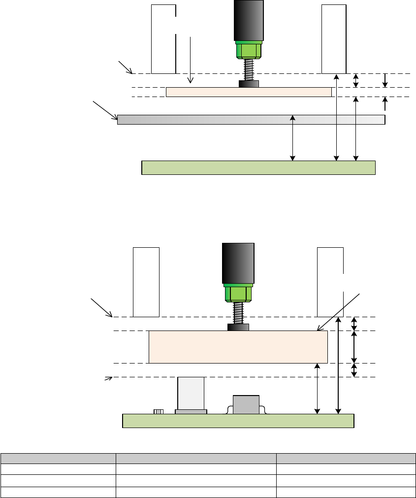
(3) For component with a diagonal line length of 86 mm or more
The vertical opening of the LNC120-8 is 91 mm. It must be operated at a position lower than LNC
120 - 8. as a component (margin, 5 mm) with a diagonal line length of 86 mm or does not enter
the opening.
Since RS-1/1R is a mechanism by which VCS light goes up and down in the cylinder, when
attracting image recognition components, it operates with a category of 12 mm or more that does
not interfere with the top face of the VCS light.
XY-axis movable height (15 mm) + component height + margin (3 mm) <LNC 120 - 8 bottom height
(28mm)
In the case of tray holder supply, it operates in category 20 mm or more so as not to interfere with
the regulation bar.
XY-axis movable height (23 mm) + component height + margin (3 mm) <LNC 120 - 8 bottom height
(28mm)
2mm
LNC120下面高さ
XY軸移動可能高さ
部品
23mm
レギュレーションバー
28mm
3mm
14
.84mm
Fig. VCS recognition height
It will also consider the height of placed components and operate it.
Placed component height + margin (3 mm) + component height + margin (3 mm)
< LNC 120 - 8 bottom height (28mm)
3
mm
LNC
120下面高さ
XY軸移動可能高さ
部品
3mm
搭載済み部品
の最大高さ
15mm
28mm
10mm
The case of the mounted component height is 12 mm
Supply equipment
Height of the placed components
Maximum component height
Feeder
12mm
10mm
Tray holder
12mm
2mm
TR8SR
12mm
2mm
Regulation bar
Height of bottom surface
of LNC120-8
XY-axis movable height
Component
Height of bottom surface
of LNC120-8
XY-axis movable height
Height of the placed
components
Component