RS-1_instruction manual.pdf - 第886页
Part 2 D etaile d Descript ion of E ach Functi on Chapter 12 Handling th e Optional Device s 12 -2 (3) Before attach ing the tape feeder on the bank, check t o see if the carrier t ape does not protrude 3 mm or more fr o…
Part 2 Detailed Description of Each Function Chapter 12 Handling the Optional Devices
12-1
Handling the Optional Devices
12.1 Feeder types
Refer to the Instruction Manual of each type of feeder for how to handle it.
This chapter describes hot to attach each type of feeder onto the machine.
12.1.1 RF series Electric tape feeder
12.1.1.1 Mounting
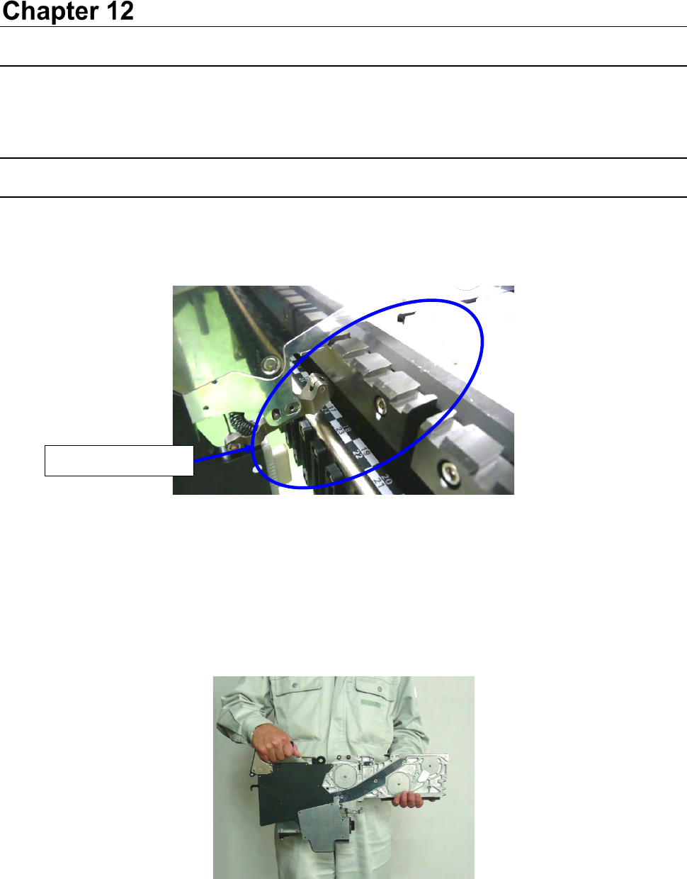
(1) Check to see if there is not any foreign substance such as an element on the following places:
fixed surface of the tape feeder, the topside of the feeder bank of a mounter, and the closely fit
section of connectors.
Figure 12.1-1
* Be sure to check to see if there is no foreign substance such as a component and dust in the
grooves of the sections A and B.
If any foreign substance is caught between thee grooves, the Guide pins (R) (F) are damaged
and it may lower the precision of the component supply position.
(2) Grasp the grip with one hand, support the slide rail with another one, and then attach the
feeder on the bank.
Figure 12.1-2
No foreign substance
Part 2 Detailed Description of Each Function Chapter 12 Handling the Optional Devices
12-2
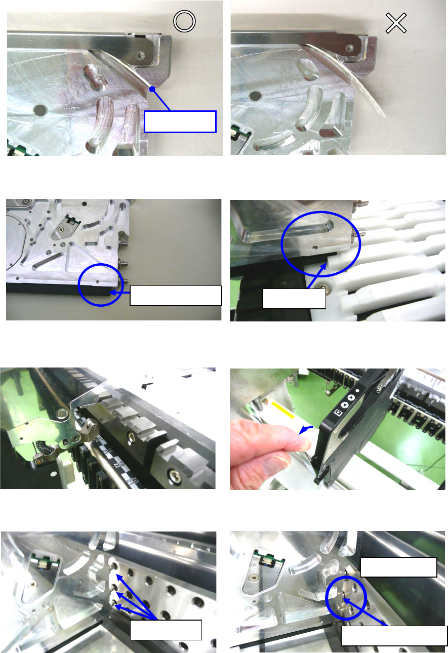
(3) Before attaching the tape feeder on the bank, check to see if the carrier tape does not
protrude 3 mm or more from the tape ejecting slot. If the tape protrudes 3 mm or more, cut it.
Before insertion, confirm that the upper cover is closed.
Figure 12.1-3 Figure 12.1-4
(4) Insert the tip of the slide rail into the groove of the guide rail.
Figure 12.1-5 Figure 12.1-6
(5) After inserting the tape feeder into the middle, pull the rock release lever, open the clamp.
Figure 12.1-7 Figure 12.1-8
(6) Hold down the tape feeder into the bank until the guide pin F hits against the side of the bank.
Figure 12.1-9 Figure 12.1-10
Tip of the slide rail
Guide rail
Guide pin F
Hit against the bank.
Contact tightly.
No Good
3 mm or less
Good
Part 2 Detailed Description of Each Function Chapter 12 Handling the Optional Devices
12-3
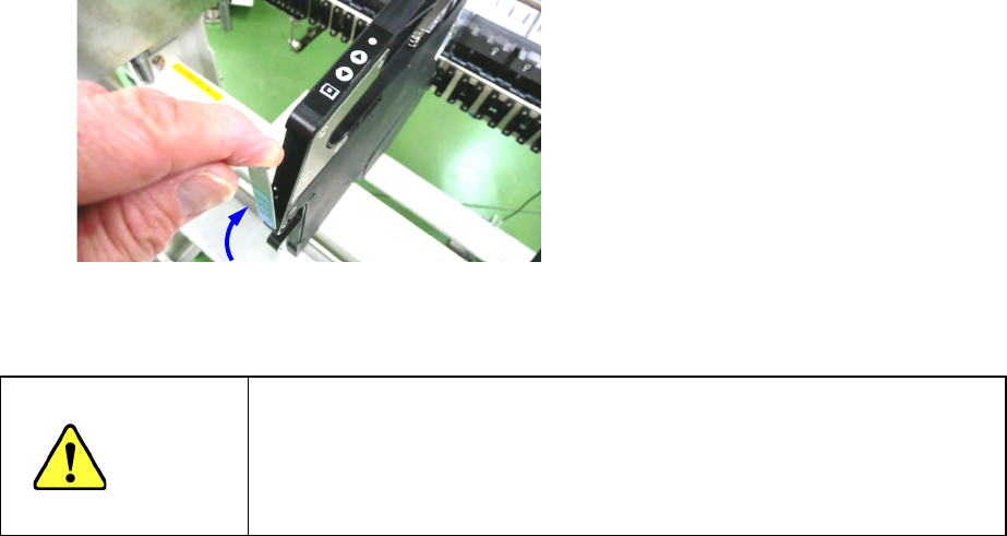
(7) Return the lock release lever and check that the feeder is clamped.
Figure 12.1-11
CAUTION
After setting feeders required for PWB production at the positions
specified with a production program respectively, set feeders not to be
used for production at the positions not occupied with the feeders above
so that any finger or hand cannot be put between the set feeders to
secure your safety.