RS-1_instruction manual.pdf - 第962页
Part 2 D etaile d Descript ion of E ach Functi on Chapter 12 Handling th e Optional Device s 12 - 78 - The message notif i es you of whether a verify check i s executed s uccessfu lly or fails. If it fails, t he message …
Part 2 Detailed Description of Each Function Chapter 12 Handling the Optional Devices
12-77
12.12.2.4 Operations
1) Single check/Continuous check
You can execute a single verify check or a continuous verify check from the menu provided on
the Production menu invoked from the “Program Editor” screen.
See Section “2.12.3 Verify check (option)” for operation.
2) When components run out
If you check the “The verification inspection is done on restart, when component run out.”
option on the “Operation option” menu, the machine will restart PWB production only after
performing a verification check for a chip component.
3) Verify check from the “Retry” list displayed during PWB production
When you replace a feeder with another one due to a component run-out error or another
reason while the “Retry” list is being displayed, you can execute the component verification
check.
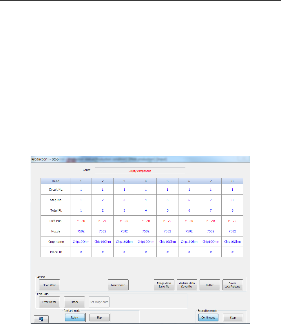
- The following screen appears when the system stops since you check the check box “Stop
system when components run out.” on the “Production (Pause)” tab invoked from the
“Operation option” dialog box.
Part 2 Detailed Description of Each Function Chapter 12 Handling the Optional Devices
12-78
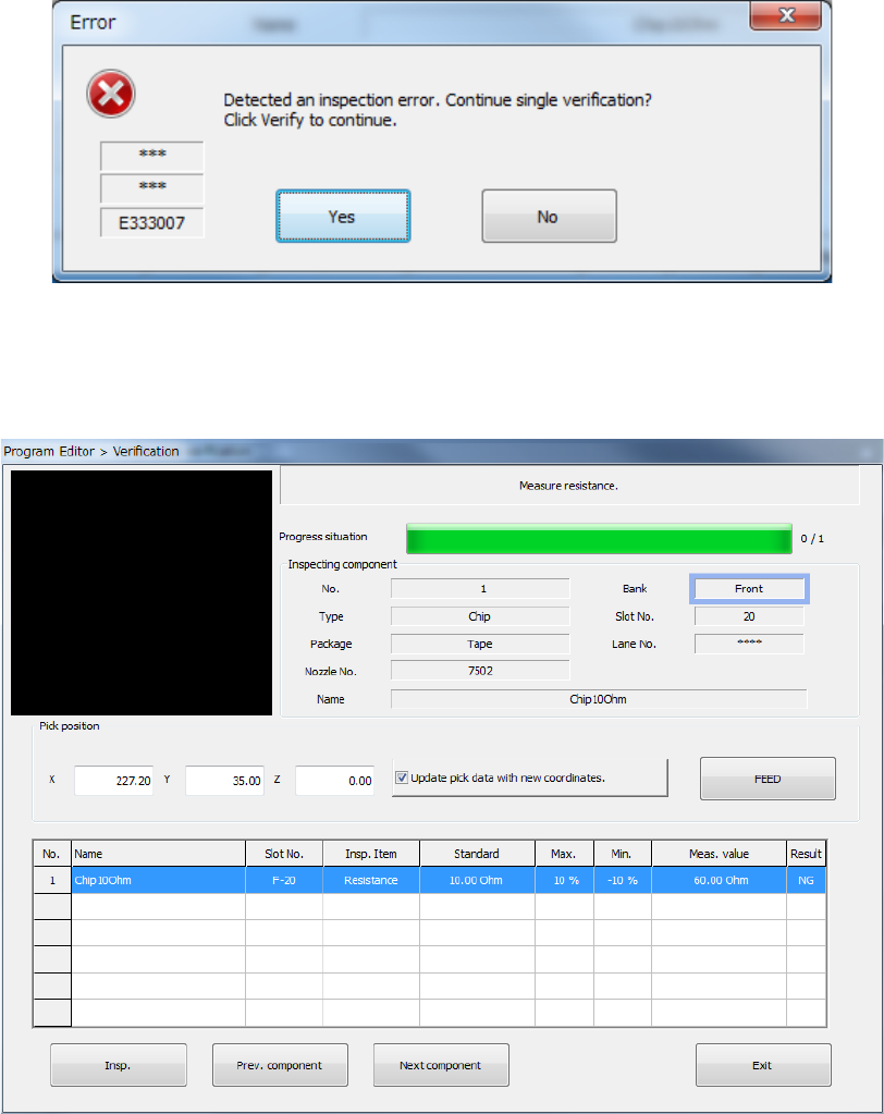
- The message notifies you of whether a verify check is executed successfully or fails.
If it fails, the message asking you whether to execute a single verify check appears on the
screen.
When you select <Yes> and press the [Single verification] button. Then, single verification is
performed.
When you select the <No> button, the machine finishes the verify check.
Part 2 Detailed Description of Each Function Chapter 12 Handling the Optional Devices
12-79
12.13 Load Control
12.13.1 Overview of the function
12.13.1.1 Low load control
When placing fragile components, the damage to the components are reduced.
After the machine finishes recognizing nozzles with the [ATC nozzle setup] command on the
“Machine Setup” screen, it automatically checks load (analyzes a failure such as a sliding failure).
By controlling load on the load cell, the machine can also check impact load against a component
when it controls load.
12.13.2 Load control nozzle
12.13.2.1 Low load control nozzle
Low load from 98 g to 507 g is controlled with the push-in amount, and the dedicated low load
control nozzle is used for this control operation.
A nozzle tip is attached on the end of the low load control nozzle, and you can replace it with a new
one at regular intervals.
Three types of nozzles: 76*1, 76*2 and 76*3 are provided for various load areas, and the machine
can support various types of components if you replace a nozzle attachment.
For a nozzle (#7601 or higher) whose load is to be controlled, you can enter the push-in amount
(“Stroke”) by the load (g) on the “Component” data of a production program, and the machine can
control low load with calculating the push-in amount based on the measurement data obtained
when the machine runs a load check.
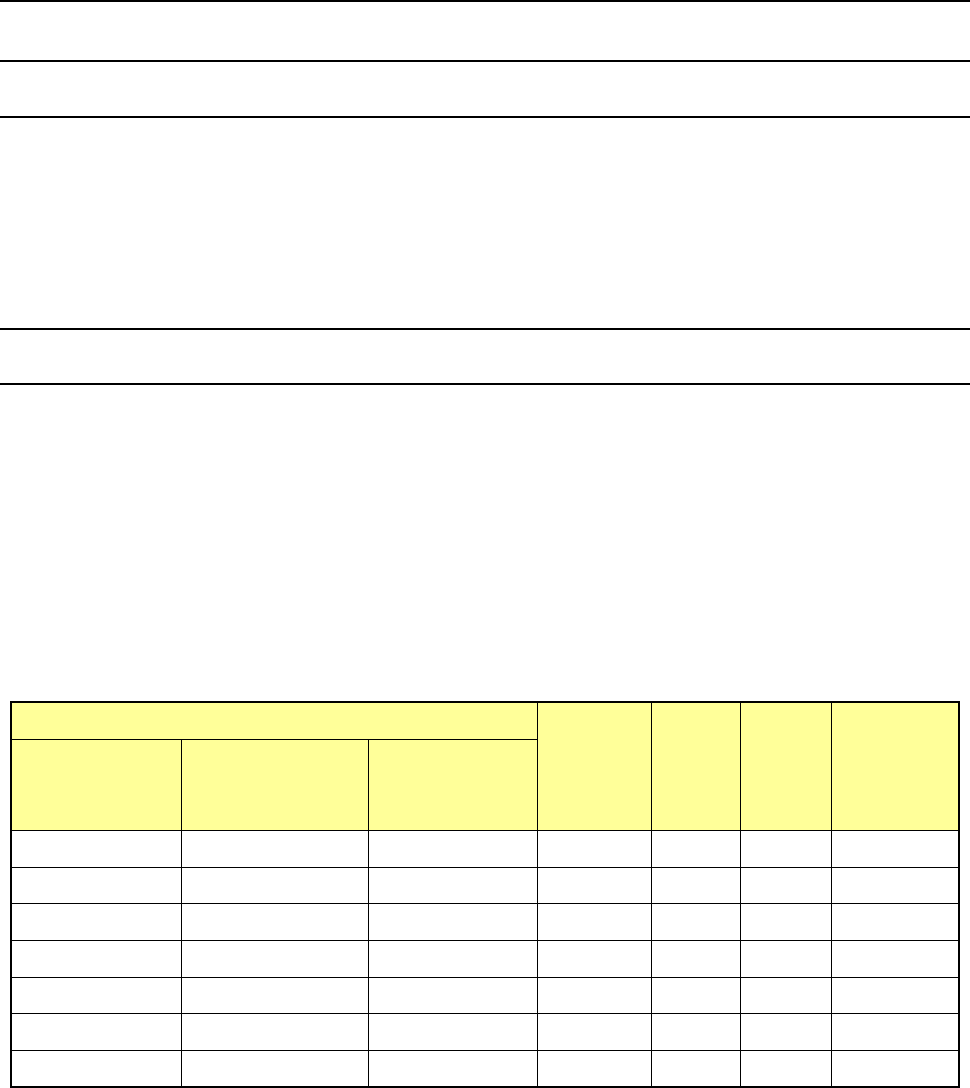
Nozzle number
Nozzle
attachment
Inside
diameter
(Ba)
Outside
diameter
(Bb)
Applicable
component
width
(mm)
76*1 type
(Load area:
98 to 135 g)
76*2 type
(Load area:
146 to 270 g)
76*3 type
(Load area:
245 to 507 g)
7611
-
-
701
φ
0.4
φ
0.75
0.45 - 0.8
7621
7622
-
703
φ
0.6
φ
1.25
0.75 - 1.5
7631 7632 - 705 φ1.15 φ1.75 1.3 - 2.7
7641
7642
-
707
φ
1.65
φ
2.25
2.5 - 3.5
7651
7652
7653
709
φ
2.2
φ
3.0
3.0 - 4.0
7661 7662 7663 711 φ3.2 φ4.0 4.0 - 6.0
7671 7672 7673 713 φ4.2 φ5.0 5.0 - 8.0
* The inside diameter and the outside diameter above indicate the dimensions of a nozzle
attachment.