RS-1_instruction manual.pdf - 第965页
Part 2 D etaile d Descript ion of E ach Functi on Chapter 12 Handling th e Optional Device s 12 - 81 12.13.3 Setup 12.13.3.1 Setting on t he “ Device enable ” screen (Enabling/disabling a load ce ll) Select the [ Setting…
Part 2 Detailed Description of Each Function Chapter 12 Handling the Optional Devices
12-80
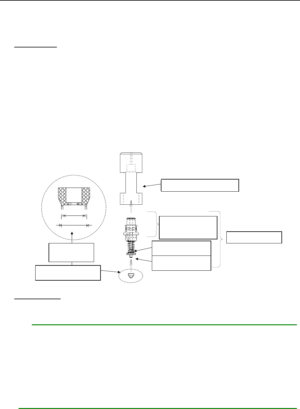
12.13.2.2 Replacing a nozzle attachment
When you replace a nozzle attachment of a low load control nozzle with another one, the nozzle can
support other types of components.
Follow the instructions below to replace a nozzle attachment with another one.
How to attach
1. Put the nozzle body (②) into the attachment push-in jig (①).
2. Insert the nozzle attachment (⑤) into the nozzle slider (④).
Pay attention so that any dust or stain cannot be adhered between the nozzle slider and the
nozzle attachment.
3. Push the nozzle attachment against the clean and flat surface, and push it enough until any
space cannot be formed between the attachment push-in jig and the flat surface.
4. Remove the nozzle from the attachment push-in jig, and then check to see if there is no
clearance between the seating face of the nozzle attachment and the nozzle slider mounting
surface, and any foreign substance is not caught between them.
① アタッチメント押込治具
③ ノズル スプリング
④ ノズル スライダ
A部: この部分は外面黒色
② ノズル ボディ
⑤ ノズル アタッチメント
内径
外径
拡大
How to remove
1. Hook your nail over the nozzle attachment, and pull it along the entire circumference of the
attachment little by little to remove it.
Notes:
1. If the seating face of the nozzle slider (the surface with which the nozzle attachment
is in contact) is scratched or damaged, it may cause an image recognition error.
When attaching/detaching the nozzle attachment, be careful not to scratch or
damage the surface.
2. If you repeat attaching/detaching a nozzle attachment, the insert hole is worn out.
It is recommended that you repeat attaching/detaching it up to ten times.
* A nozzle and a nozzle attachment are consumable goods. If any of them is defaced
or worn out, replace it with a new one.
①
Attachment push-in jig
②Nozzle body
③
Nozzle spring
④
Nozzle slider
⑤
Nozzle attachment
Enlarged
figure
Section “A”: The
external surface of
this part is black.
Outside diameter
Inside diameter
Part 2 Detailed Description of Each Function Chapter 12 Handling the Optional Devices
12-81
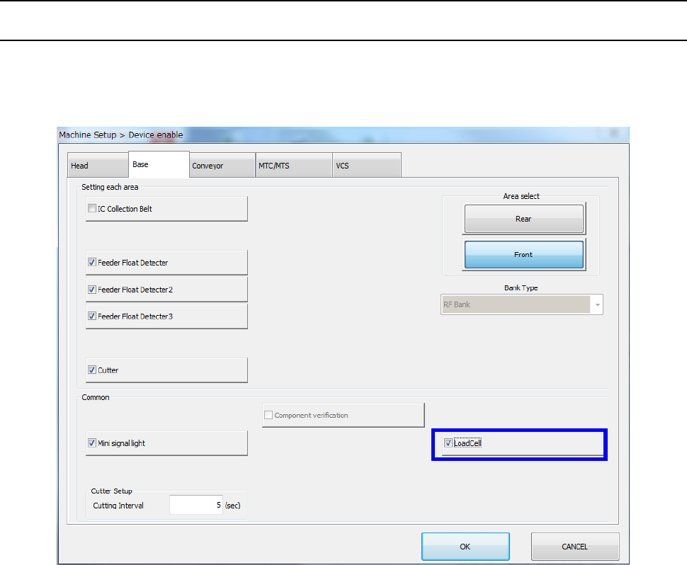
12.13.3 Setup
12.13.3.1 Setting on the “Device enable” screen (Enabling/disabling a load cell)
Select the [Setting group] command on the “Machine Setup” screen, and then the [Device enable]
command. Next, select the “Base” tab, and then check to see if a checkmark is placed in the “Load
Cell” check box.
Part 2 Detailed Description of Each Function Chapter 12 Handling the Optional Devices
12-82
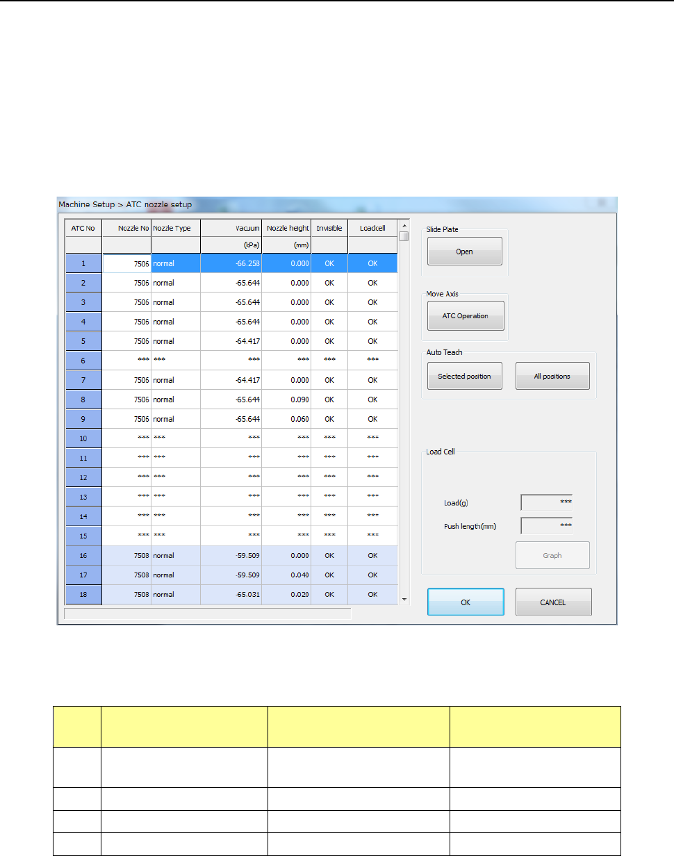
12.13.3.2 Load nozzle check
After the machine recognizes a nozzle on the “ATC nozzle setup” screen, it push in the nozzle onto
the load cell 0.1 mm by 0.1 mm until the pushing distance reaches the value specified in the “Push
length” field, and then it checks to see if the measured load is within the threshold value range to
inspect the sliding state (this is to be displayed in the “Load Cell” column).
Note that imposed load is checked for standard nozzles whose number is from 7500 to 7509 and
7680, and low load control nozzles No. 76*1, 76*2 and 76*3.
The machine automatically runs a simulation to check to see if all load of low load control nozzles
within the load input range can be corrected.
Nozzles for which the machine runs a load check and the threshold value range for checking load
are described in the table below.
No. Nozzle number
Push length to be
checked (mm)
Threshold value for
checking (%)
1
7500 to 7505,
7509 and 7680
1.5 Theoretical value ± 50
2
7506, 7507 and 7508
1.5
Theoretical value ± 40
3
76*1 and 76*2
4.5
Theoretical value ± 40
4
76*3
4.5
Theoretical value ± 40