RS-1_instruction manual.pdf - 第181页
Part 1 B asic O peration Chapter 2 Pr oduction 2- 70 “Component” data Select the “C omponent” tab disp l ayed o n the top of t he screen. (1) Li st of t he displaye d menu items The menu ite ms displayed on the left plan…
Part 1 Basic Operation Chapter 2 Production
2-69
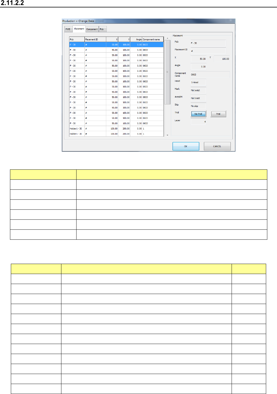
Placement data
Select the “Placement” tab displayed on the top of the screen.
(1) List of the menu items
The menu items displayed on the left plane of the screen are described in the table below.
Menu item Description
Pick Displays the supply position of a component to be placed on a board.
Placement ID Displays a placement ID of the current placement operation.
X Displays an X coordinate of a component placement position.
Y Displays a Y coordinate of a component placement position.
Angle Displays the angle of a component to be placed on a board.
Component name Displays the name of a component to be placed on a board.
(2) Placement
The descriptions of the selected menu item on the left plane of the screen are displayed on the
right plane.
Menu item Description User level
Pick Displays the supply position of a component to be placed on a board.
Placement ID Displays a placement ID of the current placement operation
X Displays an X coordinate of a component placement position.
Y Displays a Y coordinate of a component placement position.
Angle Displays the angle of a component to be placed on a board.
Component name Displays the name of a component to be placed on a board
Head Displays a head to be used to place a component on a board.
Mark Displays whether to use an area mark or not.
AreaBM Displays whether to use an area bad mark or not.
Skip Allows you to select whether to skip placement operation or not. Programmer
Trial Displays whether to place a component on a board during trial operation
Layer Displays a placement layer.
Part 1 Basic Operation Chapter 2 Production
2-70
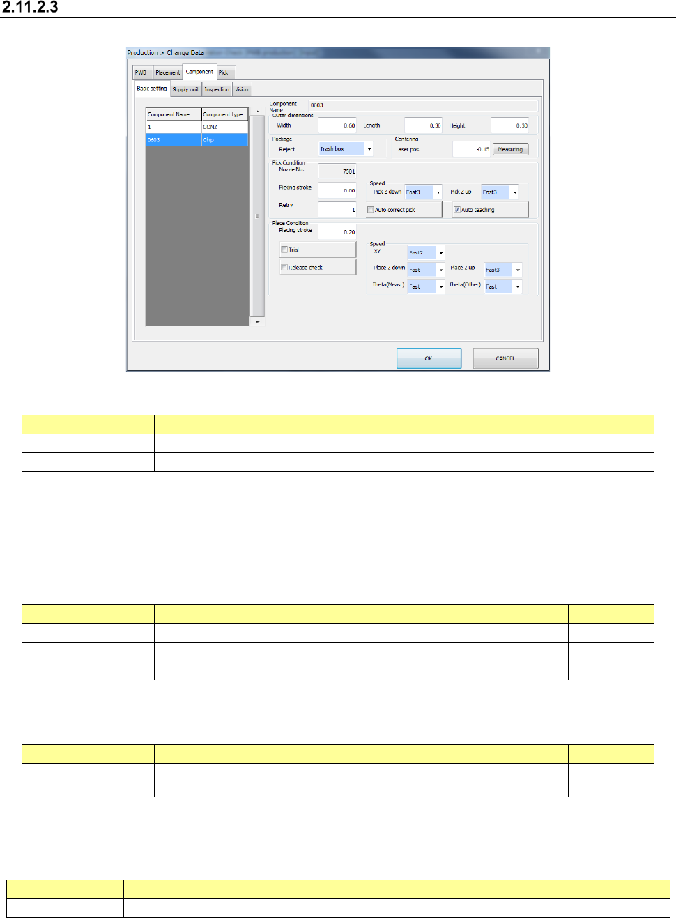
“Component” data
Select the “Component” tab displayed on the top of the screen.
(1) List of the displayed menu items
The menu items displayed on the left plane of the screen are described in the table below.
Menu item
Description
Component Name
Displays a component name.
Component type
Displays a component type.
(2) Component Name
The component name is displayed here.
(3) Outer dimensions
This menu item allows you to display and/or edit the outer dimensions of a component.
Menu item
Description
User level
Width
Enter the width of the outer dimensions of a component.
Operator
Length
Enter the length of the outer dimensions of a component.
Operator
Height
Displays the height of the outer dimensions of a component.
Operator
(4) Package
This menu item allows you to display and/or edit where to discard a component.
Menu item
Description
User level
Reject Select how to discard a component. Operator
(5) Centering
This menu item allows you to display/edit the height of laser to be used for a component. The
contents vary depending on each model.
Menu item
Description
User level
Laser pos.
Enter the laser height of a component. You can measure the laser height also.
Operator
Part 1 Basic Operation Chapter 2 Production
2-71
(6) Pick Condition
This menu item allows you to display and/or edit items on pick-ups of components.
Menu item
Description
User level
Nozzle No.
Displays the number of a nozzle that will pick up a component.
Operator
Picking stroke
Enter how much to push the tip of a nozzle when it picks up a component.
Operator
Retry
Enter the number of retries to be performed when the system fails to pick up a
component.
Operator
Auto correct pick
Select whether to correct a component pick-up position error based on a result
of recognition of a component with laser.
Operator
Auto teaching
Select whether to perform auto-teaching to track a component pick-up
position.
(8mm paper tape, 8mm emboss, the outer dimensions of a component: 0402
to 3216)
Operator
Speed Pick Z
down
Select the speed at which the Z-axis moves down at the component pick-up
position.
Operator
Speed Pick Z up
Select the speed at which the Z-axis moves up at the component pick-up
position.
Operator
(7) Place Condition
These menu items allow you to display and/or edit placement data.
Menu item
Description
User level
Placing stroke
Enter how much to push a component against the surface of a board when the
system places the component on the board.
Operator
Trial
Select whether to place a component on a board during trial production.
Operator
Release check
Select whether to check to see if a component is released with laser after the
system places it on a board.
Operator
Component skip
Select whether to skip a component without placing it on a board.
Programmer
(8) Speed
These menu items allow you to display and/or edit the speed of each axis.
Menu item
Description
User level
XY
Select the acceleration to be applied when the XY-axes move to the
component placement position after a component is picked up.
Operator
Place Z down
Select the speed at which the Z-axis moves down at the component placement
position.
Operator
Place Z up
Select the speed at which the Z-axis moves up at the component placement
position.
Operator
Theta (Means)
Select the acceleration of the theta axis to be applied when a component is
recognized with laser.
Operator
Theta (Other)
Select the acceleration of the theta axis to be applied when a component is not
recognized with laser.
Operator
(9) Supply unit
These menu items allow you to display/edit the menu items of component supply units.
Menu item
Description
User level
Component
name
Displays a component name.
-
Component
type
Displays a component type.
Package
Displays a package of a component.
-
Supply unit
Displays the attachment position of a component supply unit to be
used.
-
MTC speed
Set the operating speed of the MTC shuttle.
Operator
MTC Pickup
Specify the type of the pad on the pick-up side of the MTC.
Operator
MTC Auto
Selects both pads for the same type components during production
as long as the size of these components are in the range of □10
mm to □14 mm (□10 mm to □16 mm when a seesaw nozzle is
used), and then picks up these components.
Operator