RS-1_instruction manual.pdf - 第547页
Part 1 B asic O peration Chapter 4 Cr eating a Produc tion Progra m 4- 212 2) Explanation/ Next mode If the syst em fails to reco gnize a bank m ark, the correspo nding err or messag e is displayed in the “ Expl anation …
Part 1 Basic Operation Chapter 4 Creating a Production Program
4-211
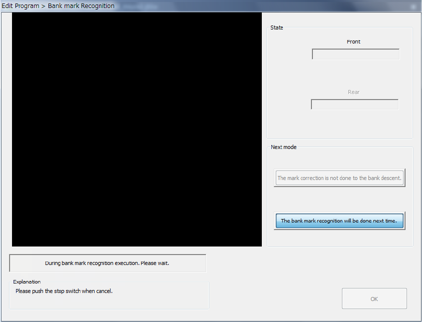
While the system is recognizing a bank mark, the screen like the one shown below appears.
The image shot with the OCC is displayed at the upper left corner of the screen.
To abort recognition of a bank mark for some reason even though the system is recognizing the
mark, press the <STOP> switch.
The system stops recognizing the mark even though it is set to continuously keep recognizing
marks, and then displays the start screen again.
1) State
• Front/Rear
The system displays the operation condition at the position on the specified station the
system is processing.
Part 1 Basic Operation Chapter 4 Creating a Production Program
4-212
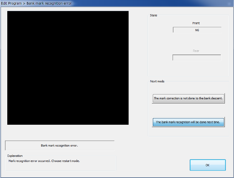
2) Explanation/Next mode
If the system fails to recognize a bank mark, the corresponding error message is displayed
in the “Explanation” column of the dialog box, and you can select any of the buttons in the
“Next mode” column.
If an error occurs, the system does not memorize the recognition results.
Select when to recognize a mark:
a) The mark correction is not done to the bank descent (the default position is to be used)
The system applies the default position to the coordinates on the bank where a
recognition error occurred, and handles that position as it is recognized already.
b) The bank mark recognition will be done next time.
The system handles a bank where a recognition error occurred as an unrecognized
bank. Therefore, the system cannot correct a bank mark.
If the system has to correct a bank mark next time, it has to recognize the mark again.
After selecting the button, press the <OK> button. The system finishes recognizing a bank
mark.
If any bank is not been recognized yet when the system is set to recognize bank marks
continuously, the system continues recognizing marks.
Part 1 Basic Operation Chapter 4 Creating a Production Program
4-213
4.5.6.4 Place
This command uses a camera to track a component placement position. You can check the
component placement position displayed on the monitor, so you can teach and edit it if the position
is not appropriate.
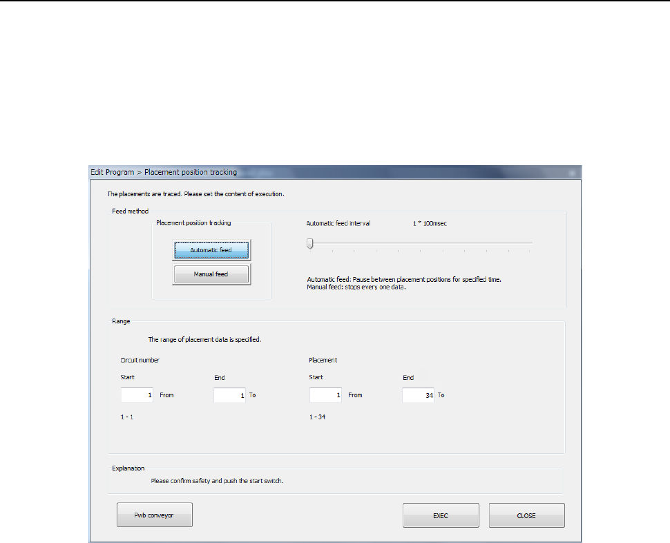
(1) Setting the tacking conditions
When you select the [Machine operation] command from the Program Editor menu, and then the
[Place] command, the following screen appears.
1) Feed method
a) Automatic feed
The camera shoots a component placement position one by one at regular intervals. The
camera stops for the time of period specified with the “Automatic feed interval” slider bar
displayed below, then moves to the next position.
• Automatic feed interval:
Use this slider bar to adjust the stop time. You can set the interval from 0.01 second (10
ms) to 5 seconds.
b) Manual feed
The system stops at each component placement position.
The operation is stopped until the user performs an operation.
2) Range
Select a circuit No. and placement point for executing tracking.
Enter the range of Placement data used for tracking: from the start point to the end point.
By default all placement positions are to be tracked.
After you specify all of the setting items, press the <Start> switch or click the <Execute>
button.
When you click the <CANCEL> button, the system returns to the previous screen.