RS-1_instruction manual.pdf - 第690页
Part 2 D etaile d Descript ion of E ach Functi on Chapter 7 Operation Option 7- 15 No. Menu item Description Status Operation an d detailed explanation 4 Auto - Corre ct pick po sition. Specify wh ether to c orre ct the …
Part 2 Detailed Description of Each Function Chapter 7 Operation Option
7-14
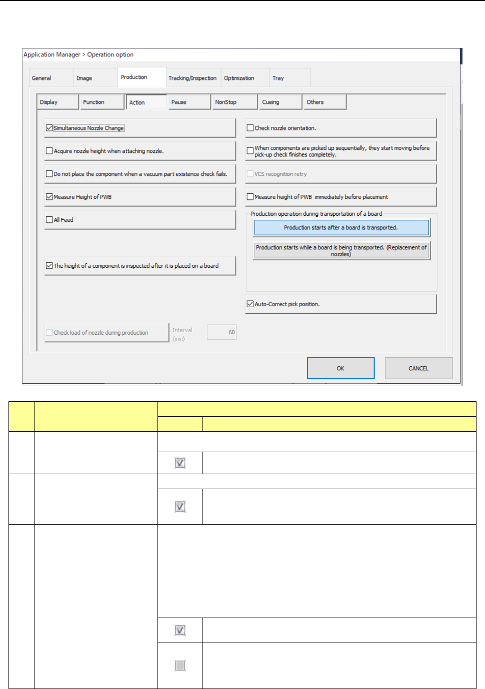
7.4.3 Action
When you press the <Action> button, the screen for setting the action options for PWB production
appears.
No. Menu item
Description
Status
Operation and detailed explanation
1
Simultaneous Nozzle
Change
Specify whether to replace nozzles at the same time.
The system replaces nozzles at the same time.
2 Check nozzle orientation.
Specify whether to measure the direction of a nozzle when it is attached.
When a nozzle is attached, the system measures the nozzle
attaching direction, and corrects the nozzle angle by its attaching
angle when it picks up, recognizes or places a component.
3
Acquire nozzle height when
attaching nozzle.
This is a function for measuring the height of a nozzle with laser when it is
attached.
By knowing the measured nozzle height, the system can obtain the more
accurate height of a component when recognizing it.
Use this function to recognize a thin component stably.
When a No. 7509 nozzle dedicated for a 0402 element is attached, the
system always measures the height of the nozzle regardless of the setting of
this function.
The system measures the height of all nozzles when they are
attached.
The system measures the height of a No. 7509 nozzle dedicated
for a 0402 element only.
(To place a 0402 element on a board, an option for supporting a
0402 element is required also.)
Part 2 Detailed Description of Each Function Chapter 7 Operation Option
7-15
No. Menu item
Description
Status Operation and detailed explanation
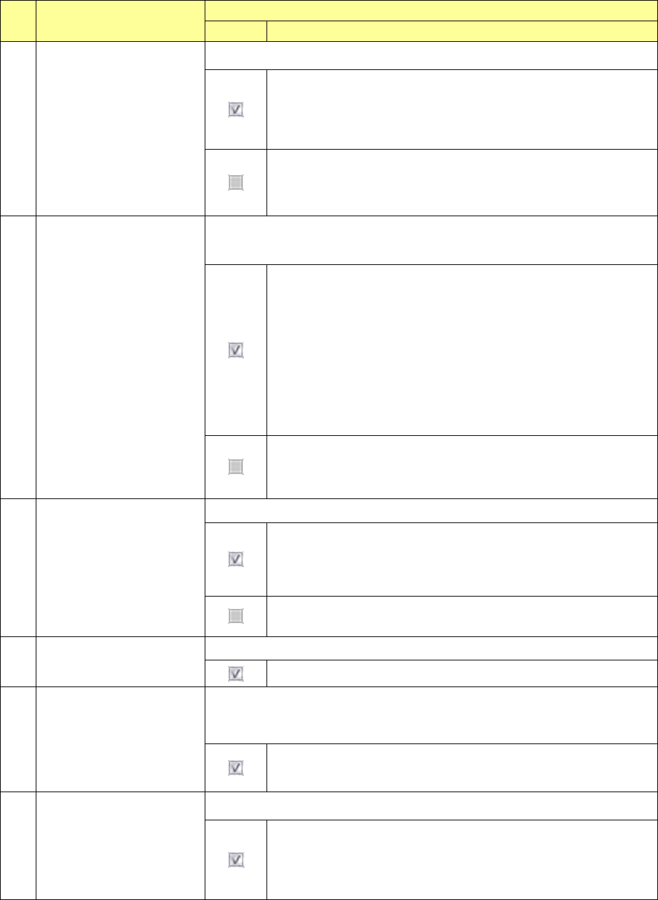
4 Auto-Correct pick position.
Specify whether to correct the component pick-up position.
The system corrects the component pick-up position based on the
result of a component centering operation with laser.
The system corrects the component pick-up position without causing
the simultaneous pick-up to be disordered by correcting the pitch in Y
direction when an electric feeder is used.
The system does not correct the component pick-up position.
The setting of the “ Auto correct pick” radio button on the “Pick
Condition” tab invoked from the “Component” data screen is
ignored.
5
Do not place the component
when a vacuum part
existence check fails.
Specify placement operation of a component that was judged not to exist with
the component existence check using vacuum, but to exist with the check using
laser.
- If the vacuum check judges that a component does not exist but the
laser check judges that a component exists when the component
existence check is performed, the system discards the component
according to the setting of the menu item “Comp. reject to” without
placing it on a board.
- If a vacuum check judges that a component does not exist before a
component is placed on a board and before a component is
recognized with a VCS (only for a component whose centering
method is set to “Vision”), the system does not perform a laser
check and discards the component according to the setting of the
menu item “Comp. reject to” without placing it on a board.
Even though a vacuum check error occurs, the system performs a
laser check when a component is picked up, when it is placed on a
board and before it is recognized with a VCS. When the laser check
judges that a component exists, the system places it on a board.
6
When components are
picked up sequentially, they
start moving before pick-up
check finishes completely.
Specify the head unit moving start timing at sequential component pick.
After pick, XY movement is started before completion of a
component existence check and the next pick is executed. At the
last pick of the pick sequence, XY movement is started after
completion of a component existence check.
After completion of a component pick check at sequential component
pick, XY movement is started and the next pick is executed.
7 Measure Height of PWB
Specify whether to measure the height of the component to be placed.
The height of the component to be laced is measured.
8
Measure PWB height
immediately before
placement.
Specify whether to measure the height of the component to be placed
immediately before placement. Unless Placement PWB height measurement
is checked off, this item cannot be selected.
The height of the PWB to be placed is measured immediately before
placement.
9
All Feed
Specify whether to feed all feeder banks at a time.
The system feeds all feeder banks at a time.
When the <Production starts while a board is being transported
(Pick-up of a component)> button is selected for the menu item
“Production operation during transportation of a board,” you cannot
select this item.
Part 2 Detailed Description of Each Function Chapter 7 Operation Option
7-16
No. Menu item
Description
Status Operation and detailed explanation
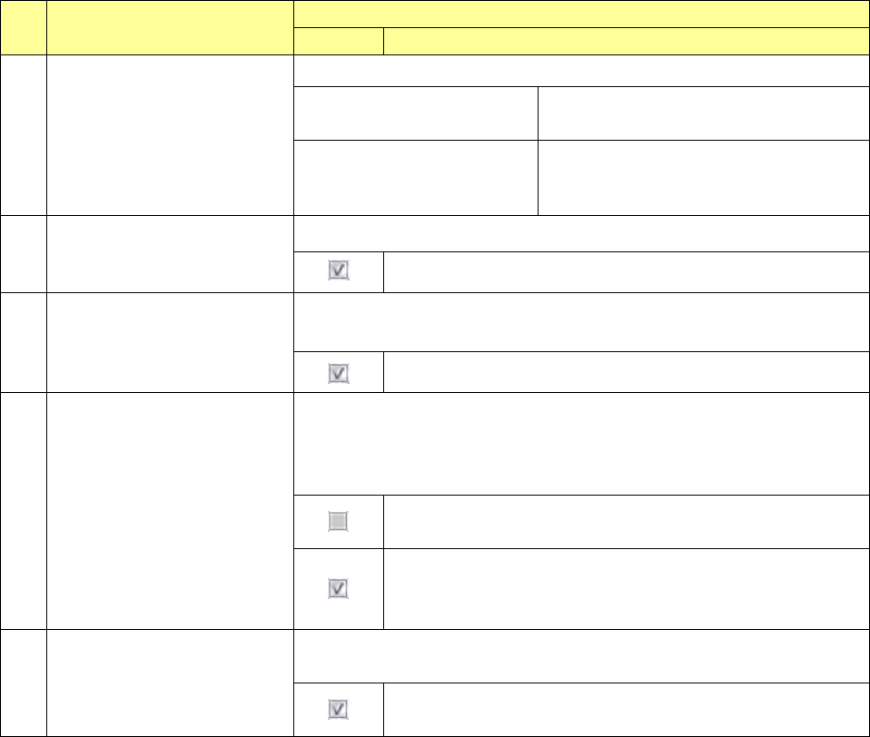
10
Production operation during
transportation of a board
Specify the production operation during transport operation.
Production starts after a board
is transported.
Production operation is started after
completion of transport operation.
Production starts while a board
is being transported.
(Replacement of nozzles)
Nozzle replacement operation is started
during transport operation.
11
VCS recognition retry
Specify whether to retry when a component is recognized with a VCS.
The system retries to recognize a component with a VCS.
12
Check load of nozzle during
production
Specify whether to check load of a nozzle during production.
You cannot select this check box when any load cell is not set.
The system checks load of a nozzle during production.
13
The feed amount is adjusted by
teaching.
Specify whether to adjust a position error of a component pick-up coordinate
Y by a feed correction value.
If a user level is lower than “Administrator,” you cannot change the current
setting.
A component pick-up coordinate Y can be changed, and the
system does not adjust the feeding amount of a feeder.
A component pick-up coordinate Y cannot be changed, and the
system adjusts the feeding amount of a feeder by teaching.
The applicable feeder is an RF8mm.
14
The height of a component is
inspected after it is placed on a
board.
Specify whether to measure the height of a component after it is placed on a
board.
The system measures the height of a component after it is
placed on a board.