RS-1_instruction manual.pdf - 第676页
Part 2 D etaile d Descript ion of E ach Functi on Chapter 7 Operation Option 7-1 Chapt er 7 Operat ion Opt ion 7.1 Overview When you select the [ Options] command f rom th e pull - down menu di spl ayed aft er you start …
Part 2 Detailed Description of Each Function Chapter 6 General-Purpose Vision Component
6-44
- If you specify only limited balls of one ball group, we cannot guarantee their recognition
accuracy.
- If the diameter check precision is the diameter ± 50 % or less, the recognizable pitch and
recognizable ball diameter are limited greatly.
- A rectangular land should be a square. (Note that the machine may recognize an element
as a lead if the ratio of the lead width to the lead length of a rectangular land is 1 : 1 or less.)
- You cannot define a ball for two different ball groups. You cannot define balls that overlap
each other either. Note that you happen to define balls in these ways if you set the wrong
ball pitch, number of ball lines and/or ball diameter.
5. Outline-recognized components
- If you define an outline-recognized component with only one type of element (corner, side or
mark) other than a lead and ball, you have to specify two or more corresponding elements. If
you specify another type of element also, you only have to specify one corresponding element
(excluding a side).
- Up to four corners can be specified for this type of component. Note that you cannot specify
two or more corners whose specified angle is the same (theta offset).
ー
θ270°
Corner
θ0°
Corner2
θ0°
Corner1
θ90°
Corner
θ180°
Corner
Although there are two corners
whose theta angle is 0 degrees, you
can specify just one corner of them.
<TOP VIEW>
- If another corner or an element (lead, rectangular land or rectangular mark) having a corner
whose angle is the same is located near one corner element, they should be far from one
another by 4 mm or more provided that the VCS (54mm view) is used.
- Up to four sides can be specified per component. However, note that two or more sides
whose specified angle is the same (theta offset) cannot be specified per component. A side
should be located on the outer frame, and its length should be half or longer of the dimension
of the component. When you specify a side (sides) only as an element, include two sides
that are orthogonal to one another.
- The linear part of the setting element should be 4.0 (±2.0 mm) or more calculated in terms of
VCS (54mm view).
- When the inside of a part is black, the thickness of the side portion should be 0.3 mm or more.
- Up to three marks can be specified per component.
- You can specify a hole as a circle mark of the reverse polarity (dark). In this case, it has to
be displayed as a circle clearly on the screen. (Note that a hole may not be displayed as a
circle clearly on the screen when a thick component is to be recognized with the perspective
light.)
- A mark should be located far from a similar-sized mark or similar-shaped and similar-sized
element (ball or circular land) by 5 mm or more provided that the VCS (54mm view) is used.
6. Notes when a general-purpose vision component data format is used
- Use this format for an element group (especially lead element group) whose positioning
precision is sufficient to be recognized. When you use this format for an element group
(especially lead element group) whose positioning precision is uncertain, a recognition error
may occur frequently.
Part 2 Detailed Description of Each Function Chapter 7 Operation Option
7-1
Chapter 7 Operation Option
7.1 Overview
When you select the [Options] command from the pull-down menu displayed after you start up the
“Operation option” utility, and then select the [Operation option] command, or when you select the
[Tool] command from the pull-own menu of the “Production” utility, and then select, the [Operation
option] command, the “Teaching” tab of the “Operation option” setting screen appears.
This utility allows you to set the operation conditions applied to data creation or production.
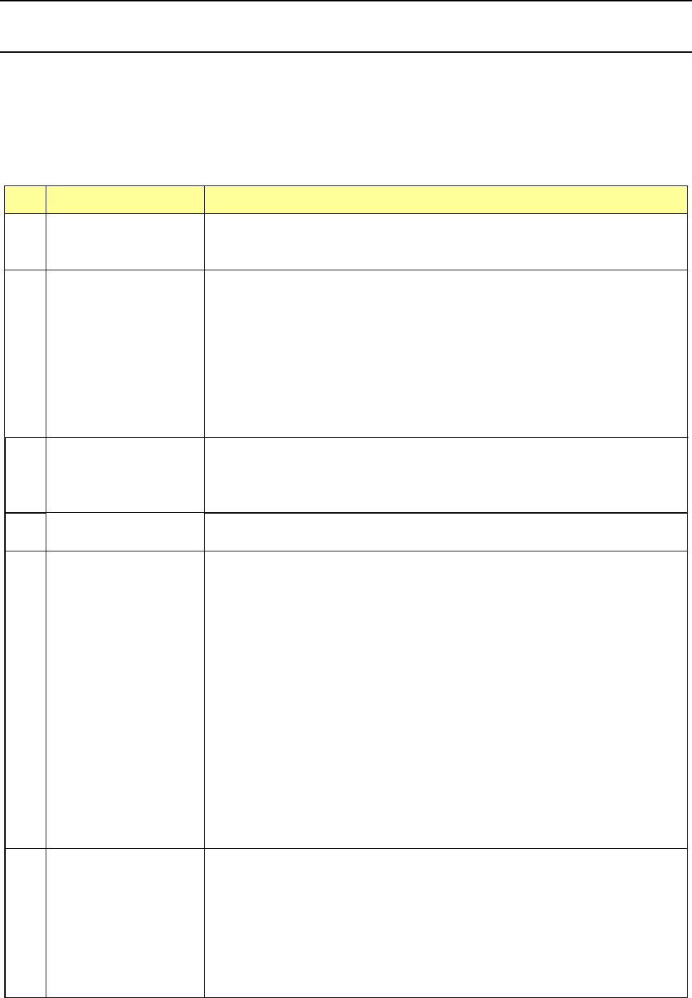
The items to be set as the operation options are shown in the table below.
No. Operation option group Option items
1 General
Explorer restricting function
Disable operation panel switches with the cover opened.
Data holding function at the end of system operation
2 Image (Teaching)
BOC alignment
Digital zoom
Use x4 zoom.
Auto teaching
Check the simultaneous pick enable range.
Do not perform auto teaching of pick height.
Mark auto teaching function
Upper limit value of mark size
Lower limit value of mark size
3 Image (Mark recognition)
Feeder bank recognition
Auto change of the threshold value of BOC mark
Lower limit value of the auto change of BOC recognition threshold value
Placement on the placement coordinates ignoring a solder recognition error.
4
Image (Mark recognizing
operation)
Prior recognition of BOC mark
Optimization of a BOC mark on each circuit
5 Production (Display)
Subtract the number of production PWBs.
Add the number of production PWBs.
Display the production screen by selecting Production Start (ONLINE).
Make no inquiry about storage at the end of production.
At non-stop production, “Non-stop production is not performed” is specified as the
default.
At non-stop production, “Production after re-clamp” is specified as the default.
At non-non-stop production, “Production after PWB inlet conveying” is specified as
the default.
Include “no components” in the number of pick errors.
Display a pick error at the start of production.
Subdivide errors at a temporary stop due to “no components.”
Worst feeder display method during production.
No output (Information of Coplanarity)
Only error electrode information (Information of Coplanarity)
All electrode information (Information of Coplanarity)
6 Production (Function)
Perform non-stop production at interruption of production.
Finish production when every circuit is provided with a bad mark.
Ignore transportation at dry run.
Control the residual number of components.
Consider the same component as an alternative feeder.
A vacuum check will not be run before production starts.
Operation at a cycle stop
Placing order of multiple circuits

Part 2 Detailed Description of Each Function Chapter 7 Operation Option
7-2
No. Operation option group Option items
7 Production (Action)
Simultaneous Nozzle Change
Check nozzle orientation.
Acquire nozzle height when attaching nozzle.
Auto-Correct pick position.
Do not place the component when a vacuum part existence check fails.
When components are picked up sequentially, they start moving before pick-up
check finishes completely.
Measure Height of PWB
Measure height of PWB immediately before placement
All Feed
VCS recognition retry
Check load of nozzle during production
Production operation during transportation of a board
The feed amount is adjusted by teaching.
The height of a component is inspected after it is placed on a board.
8 Production (Pause)
Temporary stop at occurrence of “no components”
Temporary stop at occurrence of an error
Temporary stop at a component drop
The <Replenish at no-components> button is added to the temporary stop screen.
Temporary stop at occurrence of a recognition error
Pause (When Copla check fails)
Place without checking (When Copla check fails)
Put into trash box (When Copla check fails)
9 Production (NonStop)
Non-stop operation
Alternate
Set masterBank to Rear
Non-stop operation (MTC)
Alternate (MTC)
Non-stop operation (MTS)
Alternate (MTS)
Non-stop operation (DTS)
10 Production (cueing)
Perform component cueing
Number of detected pieces
Threshold value of “existence/non-existence of components” (OCC cueing)
Threshold value of “existence/non-existence of components” (3216) (OCC cueing)
11 Production (Others)
Set 0 for the default of the scheduled number of production PWBs.
Disable the step No. input of production condition.
No feed at occurrence of a pick error when the retry is set to 0.
Pre-pick feed
Use ceramic PWBs.
Do not detect the nozzle return posture.
Tray draw speed: Low Speed 2
Hide message on production start.
High-density placement
(Print offset forward) Short side of applicable component dimensions
12
Tracking/Inspection
(Inspection enabled)
Detection of tombstone
Component dimension check
Component orientation check
Pick position offset check
Nozzle protrusion check
Component mis-release check function
Only Colinearity checked (Properties checked)
Colinearity and Coplanarity check (Properties checked)