RS-1_instruction manual.pdf - 第227页
Part 1 B asic O peration Chapter 2 Pr oduction 2- 116 General visi on component direction inspection Overview Select the [ Support ] command from the “ P roduct ” menu, an d then th e [GNR L . Vision direct ion single in…
Part 1 Basic Operation Chapter 2 Production
2-115
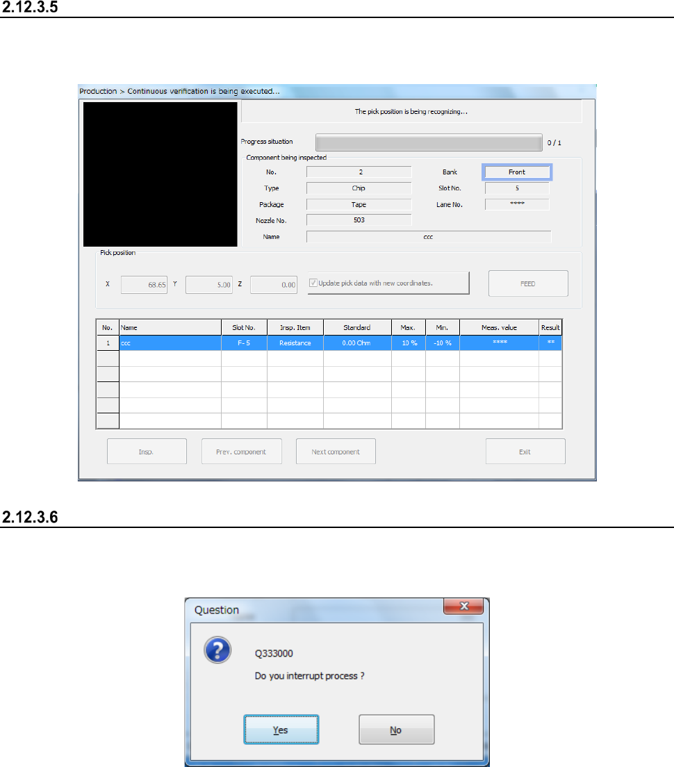
Progress of the check
While the check is continuously performed, data on a component being checked appears on the
screen, and the progress of the check and the corresponding check result are displayed on the
screen sequentially.
Aborting
To stop the inspection forcibly, press the <STOP> switch. The following message appears on the
screen.
To finish the current inspection, select the <Yes> button.
Part 1 Basic Operation Chapter 2 Production
2-116
General vision component direction inspection
Overview
Select the [Support] command from the “Product” menu, and then the [GNRL. Vision direction single
inspection] command or the [GNRL. Vision direction continuous inspection] command from the
displayed menu.
The direction of a general-purpose vision component is checked with the VCS, and two types of
check are provided: single check (GNRL. Vision direction single inspection]) and continuous check
(GNRL. Vision direction continuous inspection).
Perform this function before start of PWB production. Each check is described in the table below.
Check type Description
GNRL. Vision
direction single
inspection
When the [GNRL. Vision direction single inspection] command is selected, direction
inspection is performed for the specified component only.
GNRL. Vision
direction continuous
inspection
When the [GNRL. Vision direction continuous inspection] command is selected, the
components conforming to the conditions among all the components in the production
program data are inspected.
- You can separately check a component that the system failed to check for some
reason in Single Check mode.
Operations
(1) Applicable component size
1) SOT direction inspection
The size of the applicable SOT components are from “1608” to “4.0 mm.”
The dimensions of an electrode:
length 0.2 mm to 1.0 mm, width 0.1 mm to 1.0 mm
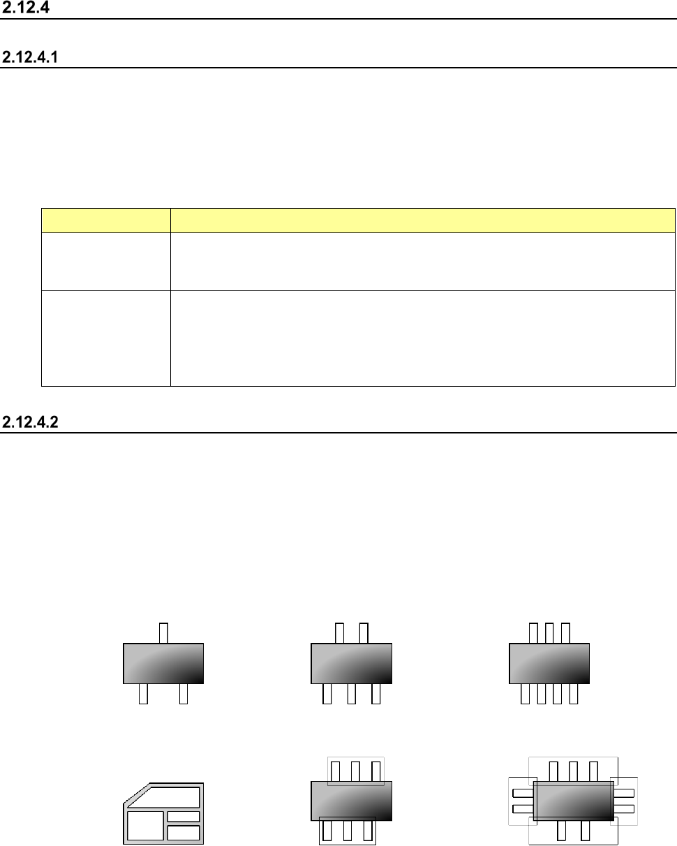
2) General-purpose vision component direction inspection
The number of element groups of applicable general-purpose vision components is 3 or less,
its component type is a lead component type, and the component shall not be rotated.
<Example of applicable components>
3 terminals 5 terminals 7 terminals
<Example of not applicable components>
Other than a lead type component Component to be rotated 3 Four element groups
(2) Inspection
1) General-purpose vision component direction inspection
The machine recognizes a picked component with a VCS to decide its angle.
Part 1 Basic Operation Chapter 2 Production
2-117
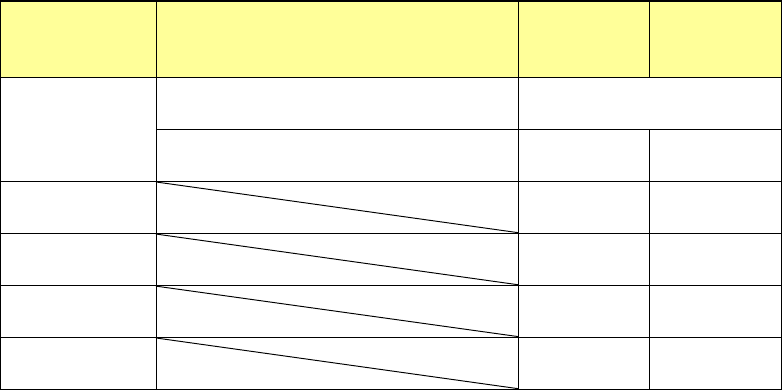
(3) Returning a component after checking it
The system returns some checked components onto their original positions, and discards other
ones depending on their packaging style after measuring them as shown in Table below.
Where to discard a component is determined according to the setting of “Compo Reject to” on
the Component data screen. When the menu item “Compo Reject to” is set to “IC Collection
Belt” or “Protect,” the system discards a component according to this setting. If a component
size is 1 mm or less, it may be placed on its side or be turned upside down when the system
returns it. Therefore, the system displays the “Question” screen to ask you how to handle it.
Note that you cannot pick up a component manually.
Packaging
style
Condition
Returning a
component
Discarding a
component
Tape
The shorter side length is 1 mm or shorter. Question dialog box *1
The shorter side length is 1 mm or longer. ○ ○ *2
Holder ○ ○ *2
Stick - ○
MTC ○ ○ *2
MTS ○ ○ *2
*1 The system displays the screen to ask you whether to return a component or discard it.
When the system enters Continuous measurement mode, it displays this “Question”
screen before continuous measurement.
*2 The system discards a component when you select “IC collection belt” or “Protect” in the
menu item “Comp reject to.”
(4) Selecting a feeder used to pick a component
If the same type of components are assigned to two or more supply units (specified in Pick
data), the system starts picking up components from one whose data was entered first of all.
(5) Changing the coordinates of a component pick-up position
If the system does not pick up a component normally, change the coordinates of a component
pick-up position by entering them manually or teaching them.