RS-1_instruction manual.pdf - 第991页
Part 2 D etaile d Descript ion of E ach Functi on Chapter 12 Handling th e Optional Device s 12 - 107 12.14.1 0 Ov erview o f a co plan arity check operatio n Operatio n of the axes o n the sensor per forme d whe n a cop…
Part 2 Detailed Description of Each Function Chapter 12 Handling the Optional Devices
12-106
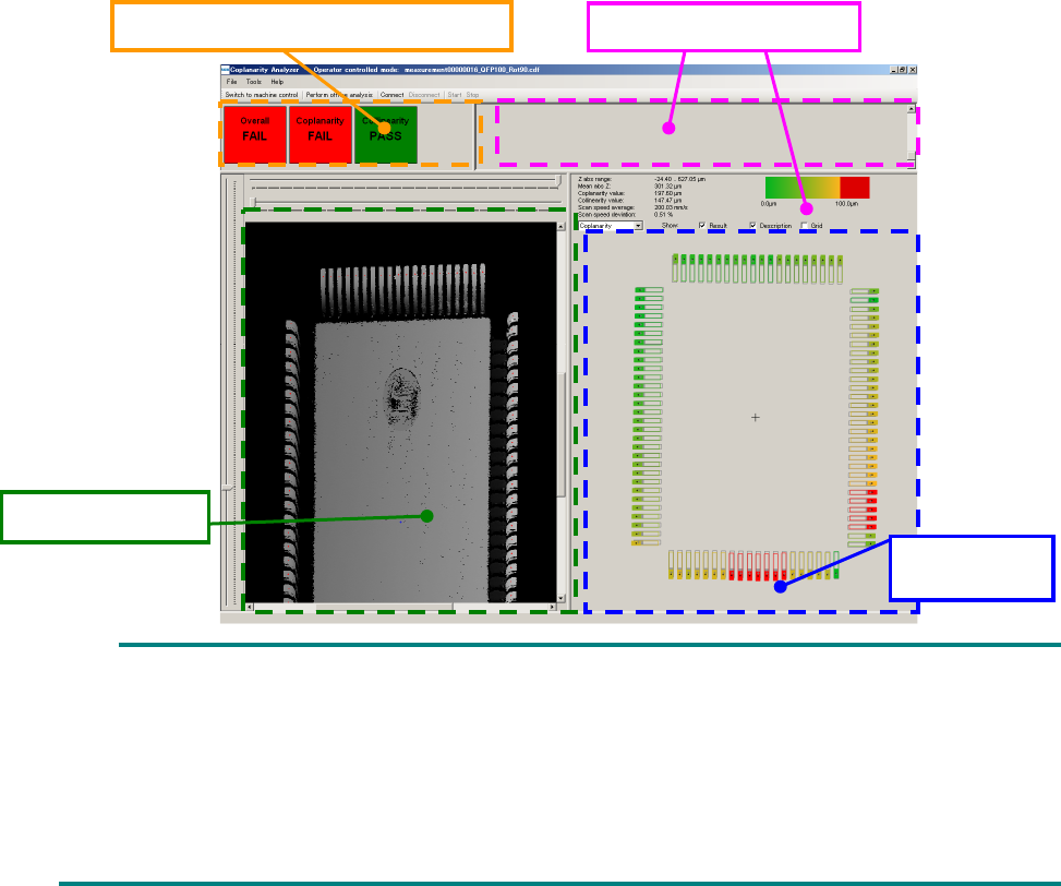
On the coplanarity screen, the “acceptance and rejection results,” “shot image,” “measurement
results” and “measurement logs” are displayed.
As the “acceptance and rejection result, the acceptance and rejection results of a coplanarity check
and those of a colinearity check, and the total results of the coplanarity check and the colinearity
check are displayed.
A 3-D image shot with the coplanarity sensor is displayed in the “shot image” area. If an electrode
is not displayed clearly enough, the measurement height is not adjusted correctly. Measure the
component height again. If the electrode is shot clearly, set a larger value for the exposure time on
the “Component” data screen.
The measured coplanarity value of an electrode is displayed in three-color gradation: green,
yellow and red in the “measurement results” area. A terminal displayed in red caused an error.
The “measurement result” of a colinearity check is displayed in preference to that of the coplanarity
check. If an error is found in both results of a colinearity check and that of a coplanarity check, only
the result of the colinearity check is displayed in the “measurement result” area.
If all terminals are displayed in green or yellow, but the “acceptance and rejection result” indicates
an error, a terminal(s) is (are) not detected correctly. Enter the correct lead width and the correct
terminal size.
The “measurement logs” area shows logs obtained during measurement. The information
displayed in this area is not used by the machine.
You cannot operate the coplanarity screen shown above.
Although the entire component is not displayed on the “shot image” area in some case, check
the shot state of the electrode displayed on the screen.
The language used on the coplanarity screen is determined according to the factory setting
regardless of the language displayed with the machine at the present. Although you switch
the displayed language to another one, the displayed language is not changed on the
coplanarity screen.
Acceptance and rejection result
Measurement logs
Measurement
result
Shot image
Part 2 Detailed Description of Each Function Chapter 12 Handling the Optional Devices
12-107
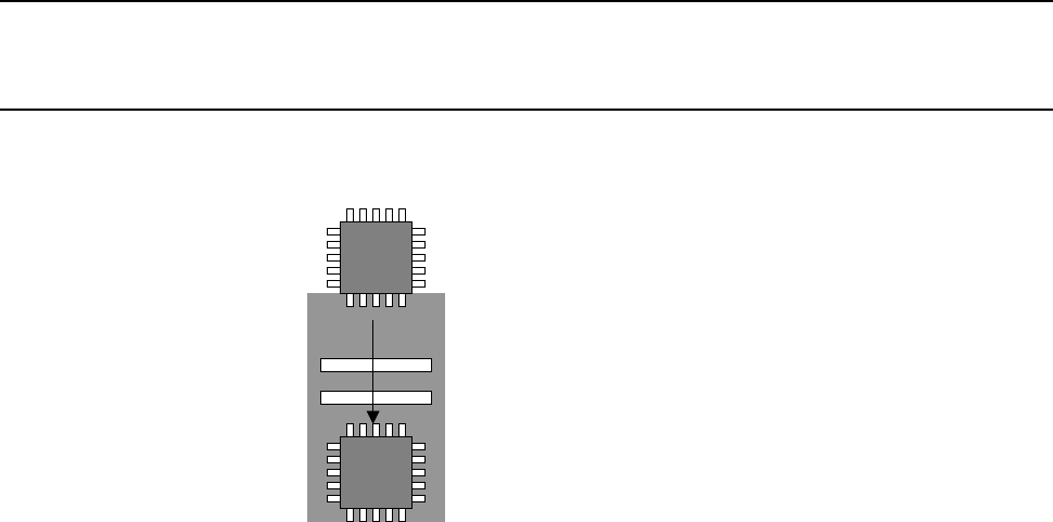
12.14.10 Overview of a coplanarity check operation
Operation of the axes on the sensor performed when a coplanarity check is run is described below.
12.14.10.1 Calculation
The sensor “scans a component in one direction, and then measures” the coplanarity.
Part 2 Detailed Description of Each Function Chapter 12 Handling the Optional Devices
12-108
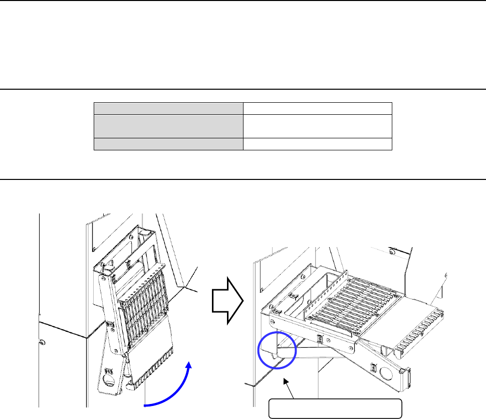
12.15 Tape set unit (applicable in and after Rev. D)
This is a stand to install the tape reel on the tape feeder. In and after Rev. D, the front side is
standard and the rear side is option. This is a fold-type stand that can be installed on the main unit
cover. Unlike the optional tape reel stand, electric power is supplied from the main unit of the
system.
12.15.1 Specifications
Number of settable feeders
14 (calculated for RF08AS)
Number of feeders to which
power can be supplied
1
Target feeder
RF series electric feeder.
12.15.2 Operating method
(1) Open the folded tape set unit and strike the end of the housed stand against the rubber part of
the main unit cover. In this status, fix it.
(2) Holding the grip of the tape feeder by hand and supporting the lower part of the feeder with
the other hand, insert the slide rail of the RF series electric feeder into the guide rail.
Strike the end of the stand.