RS-1_instruction manual.pdf - 第612页
Part 1 B asic O peration Chapter 4 Cr eating a Produc tion Progra m 4- 277 ⑧ S aving After you fin i sh teachi ng and setting all data, the syst em recognize s a compon ent. After recog ni zin g a compo nent, the sy stem…
Part 1 Basic Operation Chapter 4 Creating a Production Program
4-276
* A characteristic point(s) that can be used for recognition is (are) flashing when an area is
selected. If you include many unstable shape portions of a component or many portions not
flashing, the system may recognize an element by mistake in some cases.
● Add polarity mark window
Check off this check box when you are to create the direction judgment definition when you
select “Positioning 2” or “Positioning 3” as the “Operation mode.”
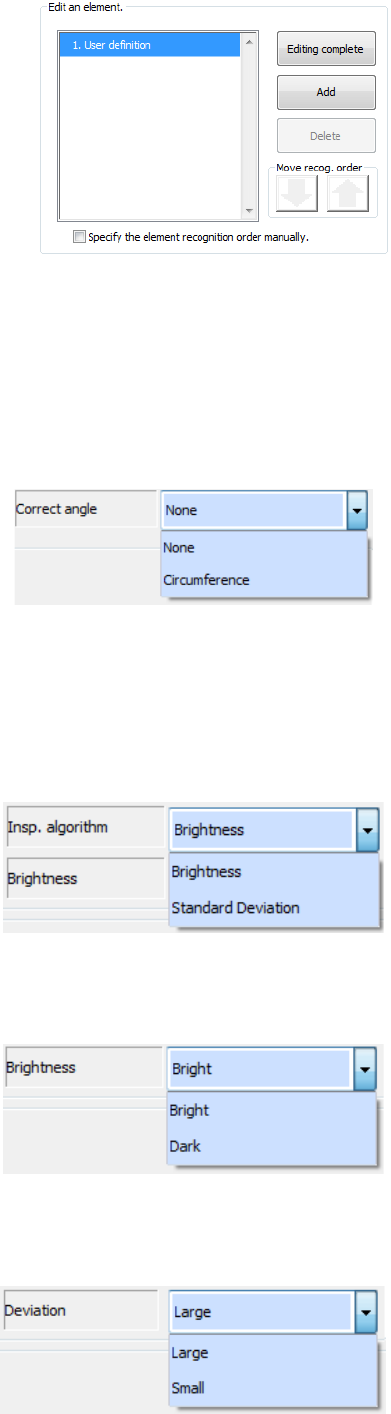
● Correct angle
- None
This is set by default.
- Circumference
Select this when an electrode(s) and/or a mark(s) are arranged on the circumference of a
component. If you select “None” for such a component, the system may recognize an
element by mistake.
● Insp. algorithm
Select this when you select “Positioning 2” as the “Operation mode.”
- Brightness
The system determines the direction by the
brightness.
- Standard Deviation
The system determines the direction by the
variance in density.
● Brightness
Specify this when you select “Positioning 2” as the “Operation mode” and “Brightness” as
the “Insp. algorithm.”
- Bright
Specify this when a bright mark or electrode in
the area for determining the direction.
- Dark
Specify this when a dark mark or electrode in the
area for determining the direction.
● Deviation
Specify this when you select “Positioning 2” as the “Operation mode” and “Standard
Deviation” as the “Insp. algorithm.”
- Large
Specify this when the density difference of the
area for determining the direction is large.
- Small
Specify this when the density difference of the
area for determining the direction is small.
Part 1 Basic Operation Chapter 4 Creating a Production Program
4-277
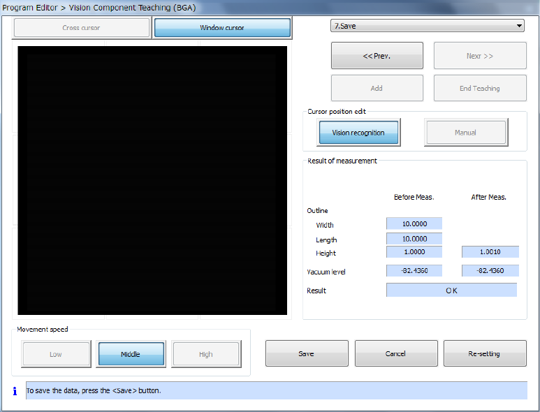
⑧ Saving
After you finish teaching and setting all data, the system recognizes a component.
After recognizing a component, the system displays the screen for saving information on the
result of measurement.
a) Press the <Save> button to save the component vision data. After the system saves the
data, this <Save> button changes to the <Exit> button.
b) Press the <Exit> button to quit the dialog box for performing the vision teaching operation,
and then return to the dialog box for setting the vision teaching operation.
c) When you press the <Cancel> button, the system discards the result of the vision teaching
operation, and then closes the dialog box for performing the vision teaching operation.
d) When you press the <Re-setting> button, the system starts the vision teaching operation
from the beginning again.
Part 1 Basic Operation Chapter 4 Creating a Production Program
4-278
4.5.7.7 Bad mark teaching
This command uses the OCC unit to check whether to produce each circuit, and teaches the
coordinates of a bad mark.
(1) Operation for teaching a bad mark
1) Teaching a bad mark
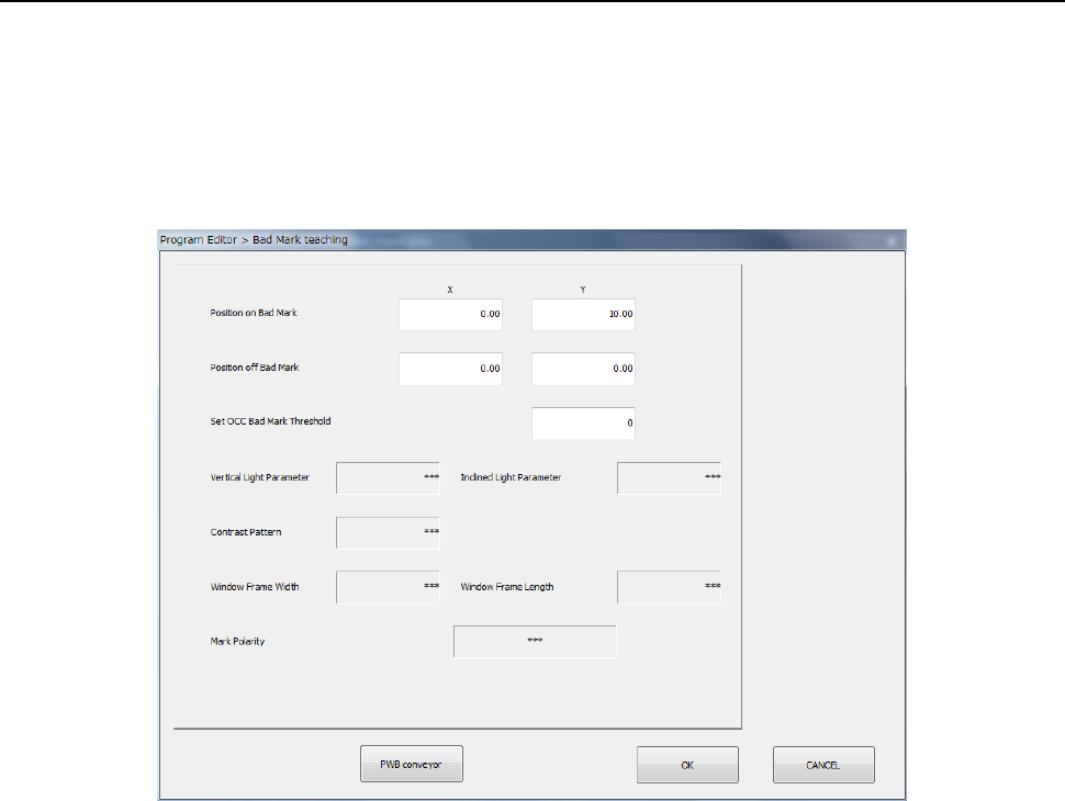
When you select the [Bad mark teaching] command, the following dialog box appears on the
screen.
① Position on Bad Mark
Specify the coordinates of the position at which a bad mark is located on a board. You can
set these coordinates by teaching them.
② Position off Bad Mark
Specify the coordinates of the position at which no bad mark is located on a board. You
can set these coordinates by teaching them. As this position, specify the position
between which the system can distinguish the contrast and that of a bad mark.
③ Set OCC Bad Mark Threshold
Set a threshold value for recognizing a bad mark.
The system automatically determines the threshold value by recognizing a position of a bad
mark and that where no mark is located with teaching operation.
④ Vertical Light Parameter
⑤ Inclined Light Parameter
⑥ Contrast Pattern
⑦ Window Frame (Width, Length)
⑧ Mark Polarity
As an initial value, “***” appears in each of the fields above.
If the system obtains the threshold value successfully when you perform teaching operation
for the “Set OCC Bad Mark Threshold” field to recognize a position of a bad mark and that
where no bad mark is located, the recognized value is set in each of these fields.