semi合集-English.pdf - 第1000页
SEMI E135-0704 © SEMI 2004 5 Transient NOTE: These data ar e for conditions where the requested power went from 3% to 33% of the full power of the RF Generator being tested. Figure 2 Example of Digital Oscillosco pe Data…
SEMI E135-0704 © SEMI 2004 4
shall continue until the RF output power has stabilized,
which typically takes a few milli-seconds. An example
of data collected from a Digital Oscilloscope for a RF
generator test is shown in Figure 5. Repeat this
measurement a minimum of 31 times and record each
condition.
11.2.5 Report the average delay time and standard
deviation between the RF Enable signal turn on signal
and the RF output power signal.
11.2.6 Change the RF Enable Signal Generator output
to a level that will turn off the DUT (per the DUT
manufacturer’s specification). Measure and record the
time delay between the RF Enable Signal Generator
signal and the RF Rectifier/Diode Detector signal with
the Digital Oscilloscope. Also record the indicated RF
output power level as measured by the RF Power
Meter. The measurement by the Digital Oscilloscope
shall continue until the RF output power has stabilized.
Repeat this measurement a minimum of 31 times and
record each condition.
11.2.7 Report the average delay time and standard
deviation between the RF Enable signal turn off signal
and the RF output power signal.
12 Reporting Test Results
12.1 Report the type of Digital Oscilloscope and the
details of the Digital Oscilloscope parameters used for
the tests, including the digitization rate used for the test.
12.2 Report the type of RF Signal Sampler used and
the type of RF Rectifier/Diode Detector used for the
test.
12.3 Report the transient response of the DUT as a
function of RF Set Point change. The data shall be
presented in both graphical and tabular forms. Report
the power level changes measured for the test.
12.4 Report the average and standard deviation of the
time delay for the RF Enable turn on and turn off
conditions. Report the average and standard deviation
of power level changes measured for the test.
13 Related Documents
13.1 IEEE
IEEE-STD-572 — IEEE Standard for Qualification of
Class 1E Connection Assemblies for Nuclear Power
Generating Stations
IEEE-STD-383 — IEEE Standard for Type Test of
Class 1E Electrical Cables, Field Splices, and
Connections for Nuclear Power Generating Stations
13.2 MIL-Spec
MIL-PRF-31031A — General Specification for
Connectors, Electrical, Plugs and Receptacles, Coaxial,
Radio Frequency, High Reliability, for Flexible and
Semirigid Cables
MIL-PRF-39012D — General Specification for
Connectors, Coaxial, Radio Frequency
MIL-STD-348 — General Specification for Radio
Frequency Connector Interfaces
MIL-STD-220B — Test Method Standard: Method of
Insertion Loss Measurement
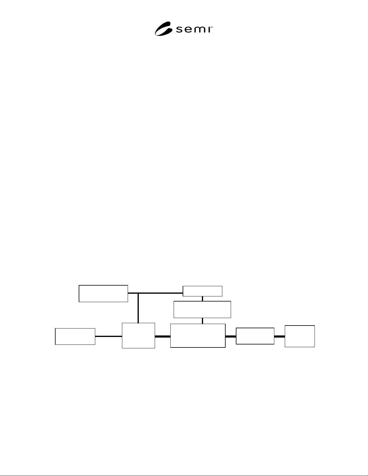
RF Si gnal Sa mple r
Directional or Non -
dire ctional Coup ler
RF Power
Meter
High-Power
RF Dummy
Load
RF S et-Poi nt/
Signa l G ener ator
RF Enab le
Signa l G ener a tor
RF
Gene r ator
(DUT )
RF Rec tifier/
Diode De tec tor
Digital Scope
NOTE: If cable assemblies are used between the output of the RF Generator (DUT) and the High-Power Dummy Load, they shall
have the same nominal impedance as the DUT and shall have a power handling capability that is consistent with the maximum
output power of the RF Generator (DUT).
Figure 1
Schematic of the Test Setup for the Measuring the Transient Response of the RF Generator (DUT) as a
Function of a Change in the Set Point
SEMI E135-0704 © SEMI 2004 5
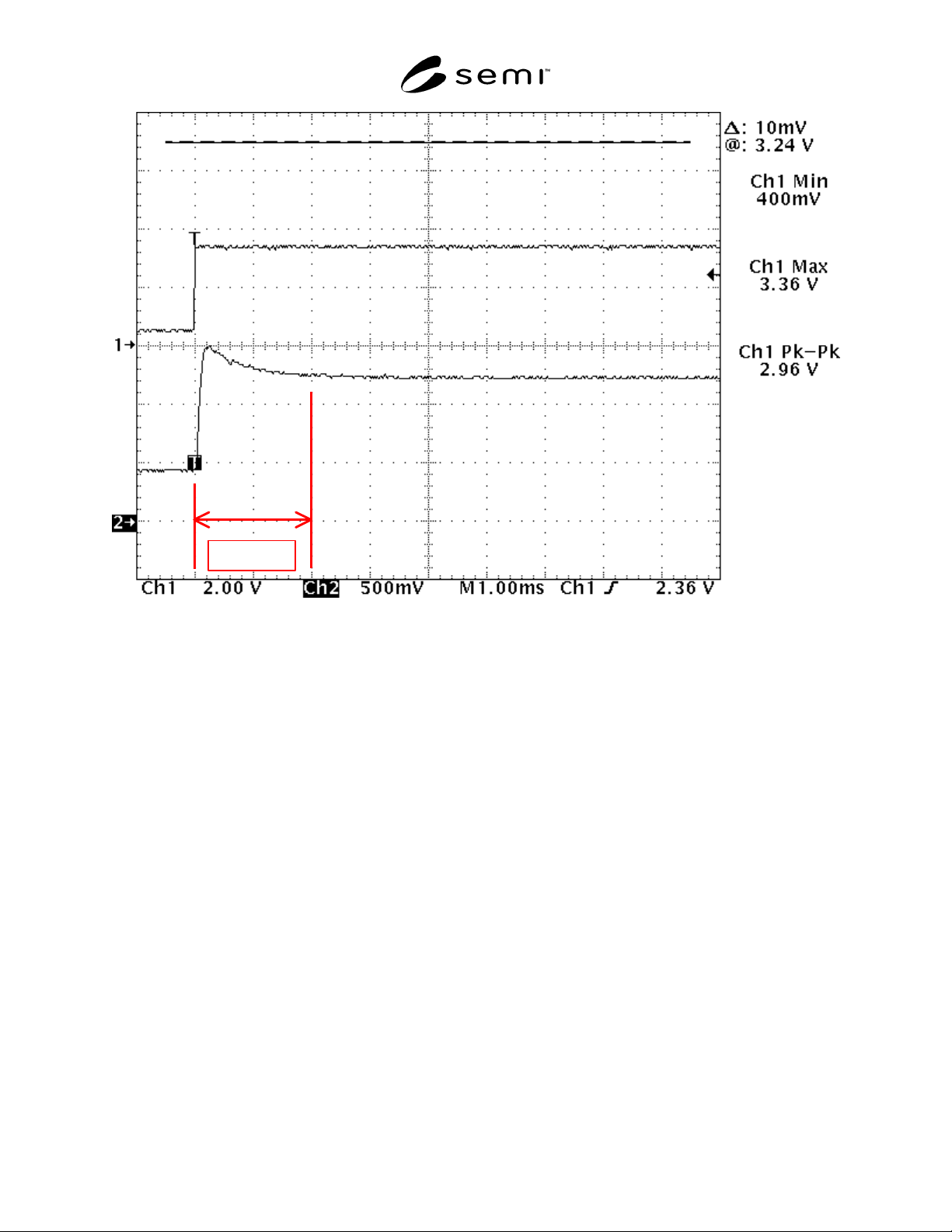
Transient
NOTE: These data are for conditions where the requested power went from 3% to 33% of the full power of the RF Generator
being tested.
Figure 2
Example of Digital Oscilloscope Data that Shows the Transient Response of the RF Output Power (Lower
Trace) Due to a Change in Set Point Signal (Upper Trace)
SEMI E135-0704 © SEMI 2004 6
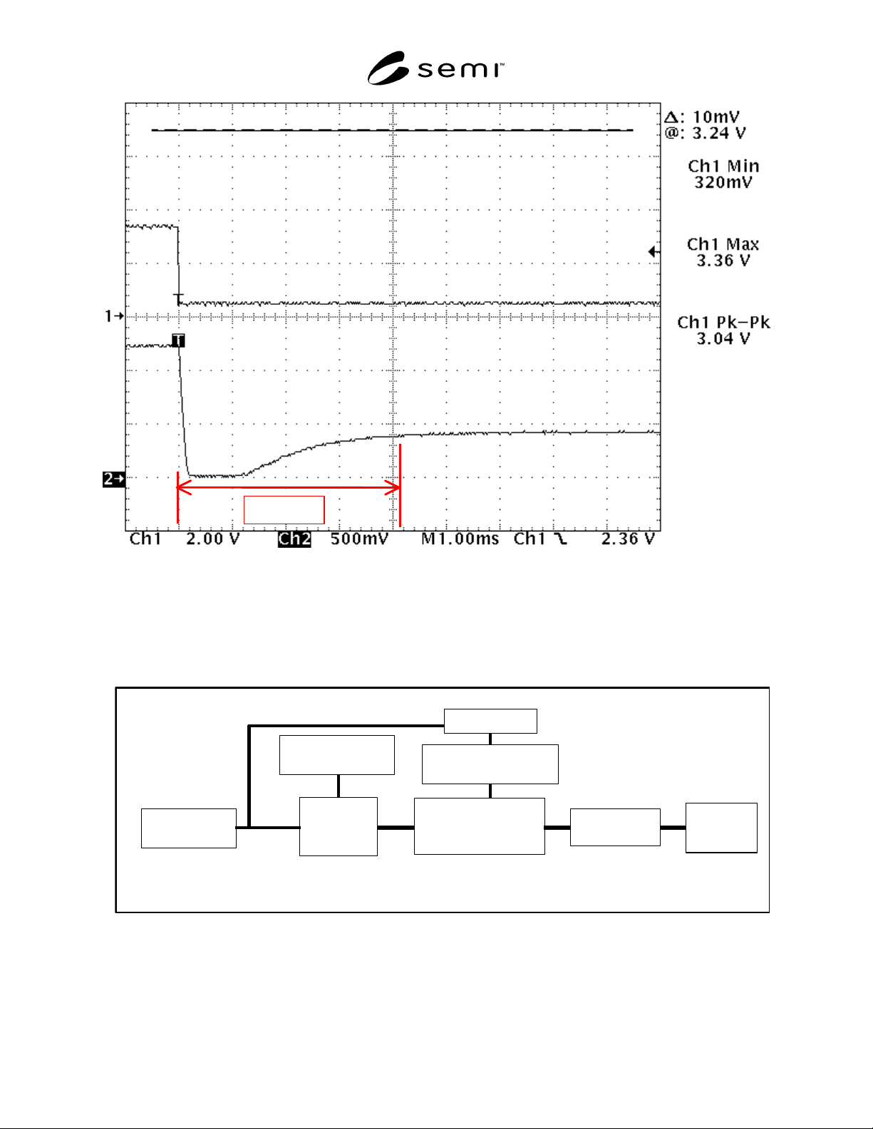
NOTE: These data are for conditions where the requested power went from 33% to 3% of the full power of the RF Generator
being tested.
Figure 3
Example of Digital Oscilloscope Data that Shows the Transient Response of the RF Output Power (Lower
Trace) Due to a Change in Set Point Signal (Upper Trace)
RF Signal Sample
r
D
irectional or
N
ondirectional
RF Powe
r
Mete
r
High-Power
RF Dummy
Load
R
F
Generator
(
DUT
)
RF Rectifier
/
Diode Detecto
r
Digital Scope
RF Enable
Signal Generato
r
RF Set-Point
/
Signal Generato
r
NOTE: If cable assemblies are used between the output of the RF Generator (DUT) and the High-Power Dummy Load, they shall
have the same nominal impedance as the DUT and shall have a power handling capability that is consistent with the maximum
output power of the RF Generator (DUT).
Figure 4
Schematic of the Test Setup for the Measuring the Transient Response of the RF Generator (DUT) as a
Function of a Change in the RF Enable Signal