semi合集-English.pdf - 第459页
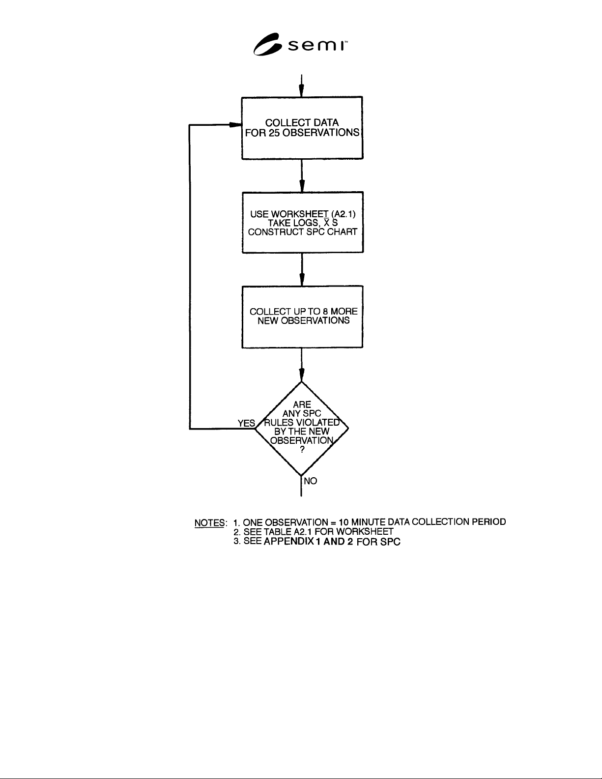
SEMI E66-1103 © SEMI 1997, 2003 8 Figure 6 Statistical Validity Subr outine 12.1 Procedure for Direct Sampling — See Figu res 5 and 6. 12.1.1 Background Count Determination — Insert spool piece between points A and B (se…
SEMI E66-1103 © SEMI 1997, 2003 7
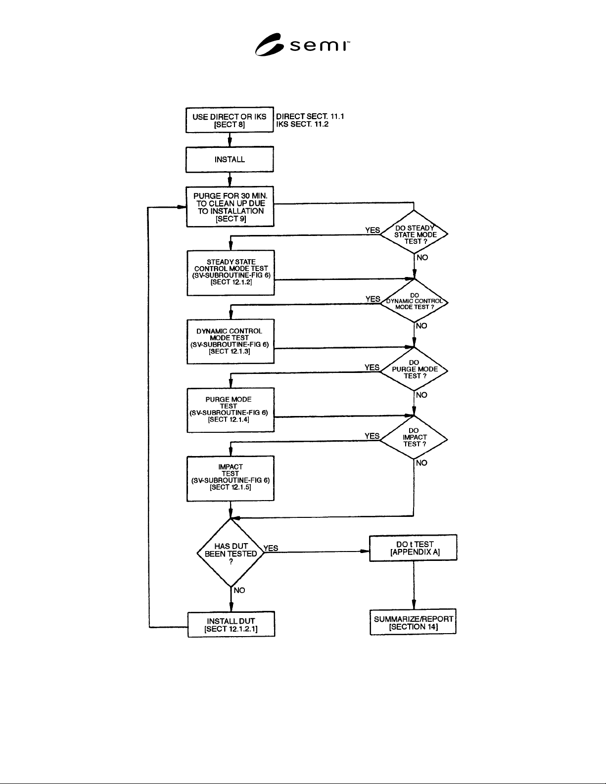
Figure 5
Particle Test Flow Chart
SEMI E66-1103 © SEMI 1997, 2003 8
Figure 6
Statistical Validity Subroutine
12.1 Procedure for Direct Sampling — See Figures 5
and 6.
12.1.1 Background Count Determination — Insert
spool piece between points A and B (see Figure 1).
12.1.2 Steady State Control Mode Background Test —
Set supply MFC (SFC) to the intended test flow value
of the DUT. For this test, the 100% full scale value is
recommended.
12.1.2.1 Count particles for the time necessary to
achieve a stable particle level.
12.1.3 Dynamic Control Mode Background Test —
Cycle the SFC from 10% to 100% of the DUT’s rated
flow. The cycle period is equal to two times the settling
time of the DUT with the longest settling time. (This
will ensure that all MFCs in a given test are tested at the
same cycle time.)
SEMI E66-1103 © SEMI 1997, 2003 9
12.1.3.1 Count particles for the time necessary to
achieve a stable particle level.
12.1.4 Purge Mode Background Test — Set the SFC to
100% of the rated flow of the DUT.
12.1.4.1 Count particles for the time necessary to
achieve a stable particle level.
12.1.5 Impact Background Test (optional) — Set the
SFC to the intended flow value of the DUT. For this
test, the 100% full scale (FS) value is recommended.
12.1.5.1 Maintain the test flow in the spool piece to
achieve a constant particle level. Strike the spool piece
once a minute (using the mechanical shock device) until
a constant particle level is achieved. (See Figure 4.)
12.1.5.2 Count particles for the time necessary to
achieve a stable particle level.
12.1.6 Steady State Control Mode Test — Set SFC to
10% setpoint of the DUT’s rated flow.
12.1.6.1 Remove the spool piece by disconnecting the
downstream fitting and then the upstream fitting.
Immediately install the test component in a fully open
position by connecting the upstream fitting and then the
downstream fitting. Take extreme care to minimize
contamination of the test apparatus during this
operation.
12.1.6.2 Set the SFC in purge mode (emulates tubing).
12.1.6.3 Set the DUT to the desired flow. For this test,
the 100% full scale value is recommended.
12.1.6.4 Count particles for the time necessary to
achieve a stable particle level.
12.1.7 Dynamic Control Mode Test — Keep the SFC
in purge mode (emulates tubing).
12.1.7.1 Cycle the DUT from 10% to 100% of the
DUT’s rated flow. The cycle period is equal to two
times the settling time of the DUT with the longest
settling time. (This will ensure that all MFCs in a given
test are tested at the same cycle time.)
12.1.7.2 Count particles for the time necessary to
achieve a stable particle level.
12.1.8 Purge Mode Test — Set SFC to 100% of the
DUT’s rated flow.
12.1.8.1 Operate DUT in the purge mode until a stable
particle level is achieved.
12.1.9 Impact Test (optional) — This test is to
immediately follow the purge mode test.
12.1.9.1 Keep the SFC set to 100% of the DUT’s rate
flow.
12.1.9.2 Operate the DUT in the purge mode until a
stable particle level is achieved.
12.1.9.3 Strike the DUT once a minute until consistent
particle transients are achieved using the mechanical
shock device. (See Figure 4.)
12.1.10 Background Test — Repeat all background
tests performed in Section 12.1.1.
12.1.10.1 Procedure for Isokinetic Sampling — Follow
the procedures described in Section 12.1, with the
following exceptions:
12.1.10.2 To establish the background, see Figure 2
and the example below. With the spool piece in place,
the throttle valve V1 fully open, and the bypass MFC in
purge mode, set the SFC to the maximum inlet flow of
the IKS. Adjust V1 and monitor the flow through the
bypass MFC until the difference between the SFC flow
and the bypass MFC flow is equal to the intended test
flow of the DUT. The throttle valve V1 should remain
fully open for all other tests that use the test set-up in
Figure 2.
Example
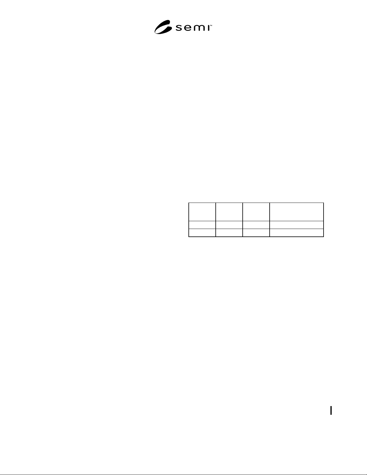
Given Test
Flow:
Set SFC
Flow:
Adjust V1 for Bypass
MFC Flow:
25 slpm 30 slpm 5 slpm
50 slpm 100 slpm 50 slpm
12.1.10.3 During steady state and dynamic testing of
the DUT, use the bypass MFC to make up the
difference between the intended flow value of the DUT
and the maximum inlet flow of the sampler selected
from Table 1.
13 Data Analysis
13.1 Appendix 1 contains information on statistical
process control charting. Appendix 2 contains
information on performing the t-test, a statistical
method of comparing the mean background particle
count with the mean device particle count.
14 Data Presentation
14.1 The following test conditions are to be reported in
the data presentation:
14.1.1 Date and time of test
14.1.2 Operator
14.1.3 Test flow rate (sccm)
14.1.4 Test pressure (kPa)
14.1.5 Ambient temperature (°C)
14.1.6 MFC orientation