semi合集-English.pdf - 第4693页
SEMI C3.35-11 01 © SEMI 1988 , 2001 5 required. This can be obt ained by preparing a standard of w a ter balance n itrogen and mixing it with dr y hydrog e n chl oride using a dynamic gas blender with mass flow controlle…
SEMI C3.35-1101 © SEMI 1988, 2001 4
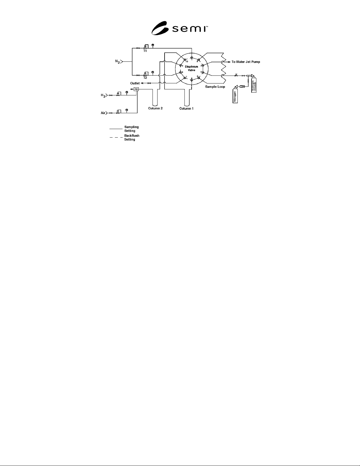
4.6 Methane and Acetylene — This procedure is for the
determination of methane and acetylene in hydrogen
chloride. Samples from gas phase are analyzed by a gas
chromatograph with a flame ionization detector. A
backflush is used to keep the main component from the
detector. (See Figure 2.)
4.6.1 Detection Limit — 0.1 ppm for each impurity.
4.6.2 Instrument Parameters
4.6.2.1 Column:
Alumina-GC, 60-80 mesh, Chromopack, 1.5 m (5 ft) by
2 mm ID (1/8 in OD) ss;
or
Alumina-GC, 60-80 mesh, Chromopack, 2 m (6.7 ft) by
2 mm ID (1/8 in OD) ss;
or equivalent.
4.6.2.2 Detector Sensitivity: 0.012 coulombs/gram.
4.6.2.3 Carrier Flows (1 and 2): 30 mL/min helium.
4.6.2.4 Set the following rates as specified by the
instrument manufacturer.
Support Gases:
Hydrogen Flow: 30 mL/min.
Air Flow: 450 mL/min.
4.6.2.5 Temperatures:
Detector 200°C
Column Oven 100°C
4.6.2.6 Sample Volume: 0.5 mL.
4.6.2.7 Sample Flow: 200 mL/min.
4.6.3 Calibration Standard — 5 to 10 ppm each
methane and acetylene in nitrogen.
4.6.4 Operating Procedure
4.6.4.1 Install switching valve and columns.
4.6.4.2 Adjust carrier gas flows:
Switching valve in injection position
• Set a flow rate of 30 mL/min, with the regulator T1
measured at the FID outlet.
Switching valve in backflush position
• Set a flow rate of 30 mL/min, with the regulator T2
measured at the FID outlet.
• Set a flow rate of 30 mL/min, with the metering
valve, measured at the pre-column outlet.
A last adjustment between the injection and backflush
position may be carried out by the FID signal. For this,
the baseline is recorded in the injection and backflush
position. With the regulator T2, the flow rate is changed
so far as there is no offset in the baseline while
switching.
4.6.4.3 Adjust hydrogen and air flows and ignite the
burner, following the instrument manufacturer's
instructions. Allow the system to stabilize for at least 30
minutes.
4.6.4.4 Determine backflush time — Inject calibration
standard and leave the switching valve in inject position
until all components have been eluted. Determine
retention times for methane and acetylene. Choose
backflush time so that the acetylene peak is completely
registered.
4.6.4.5 Inject the calibration standard. Backflush at the
time determined in Section 4.6.4.4. Record the
retention times and peak areas.
4.6.4.6 Inject the sample to be tested in the same
manner as the calibration standard. Backflush at the
time determined in Section 4.6.4.4. Record the
retention times and peak areas.
4.6.4.7 Repeat Section 4.6.4.5.
4.6.4.8 Compare the average peak areas of the
calibration standard with those of the hydrogen chloride
sample being tested. Calculate the concentration of each
impurity, using the formula below. The results may not
exceed the specifications in Section 3 of this standard.
Sample Peak Area
Standard Peak Area
×
Concentration
of Standard
=
Concentration
of Sample
4.7 Water — This procedure is for the determination of
trace moisture (water) in hydrogen chloride gas using a
continuous flowing, cooled-surface condensation point
hygrometer.
4.7.1 Detection Limit — 1.0 ppm.
4.7.2 Flow Requirements
4.7.2.1 Set the sample flow rate and pressure in
accordance with the instrument manufacturer’s
instructions.
4.7.3 Calibration Standards
4.7.3.1 A calibration thermometer designed to indicate
temperatures in the –89°C (–121°F) range is required.
NOTE 4: The National Institute of Standards and Technology
(NIST) provides calibration services for the thermometers
used in condensation point hygrometers.
4.7.3.2 A calibration curve representing water added to
dried hydrogen chloride vs. condensation point is
SEMI C3.35-1101 © SEMI 1988, 20015
required. This can be obtained by preparing a standard
of water balance nitrogen and mixing it with dry
hydrogen chloride using a dynamic gas blender with
mass flow controllers or calibrated flowmeters. The
hydrogen chloride gas can be dried by passing it over
activated molecular sieve (5A) or magnesium
perchlorate.
NOTE 5: This method is not applicable if other constituents
in the gas will condense before the moisture condensation,
e.g., carbon dioxide or oil.
4.7.4 Operating Procedure
4.7.4.1 Obtain a continuous flow of sample gas from
the source using a clean stainless steel sampling line
which has been purged dry after exposure to ambient
moisture.
NOTE 6: The sampling system and hygrometer must be
designed to operate under the sample pressure, or the sample
pressure must be reduced to accommodate the pressure
restrictions of the analytical hygrometer using a regulator with
a diaphragm of stainless steel or other suitable material.
4.7.4.2 After prepurging with a dry gas, allow the
sample gas to flow through the sampling system and the
condensation point hygrometer for one-quarter hour to
two hours to allow the entire system to reach
equilibrium with regards to moisture content.
4.7.4.3 After equilibrium has been reached, cool the
mirror to determine the actual condensation point of the
sample.
4.7.4.4 Continue to verify the condensation point for at
least 30 minutes after a stable reading has been
confirmed.
4.7.4.5 Correct the condensation point reading from the
measured pressure to 1 atm of pressure. The result may
not exceed the specification in Section 2 of this
standard.
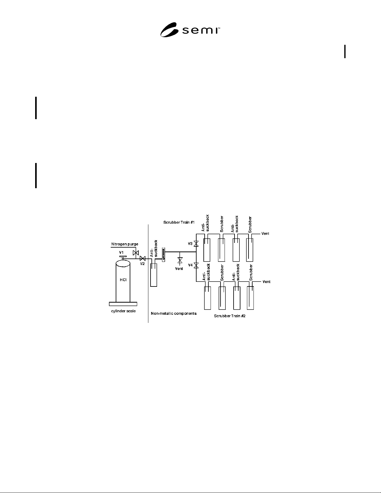
Figure 1
Metals Analysis Sampling Apparatus Vapor Phase Hydrolysis
SEMI C3.35-1101 © SEMI 1988, 2001 6
Figure 2
Column Configuration for the Analysis of Methane, Acetylene
NOTICE: These standards do not purport to address safety issues, if any, associated with their use. It is the
responsibility of the user of these standards to establish appropriate safety and health practices and determine the
applicability of regulatory limitations prior to use. SEMI makes no warranties or representations as to the suitability
of the standards set forth herein for any particular application. The determination of the suitability of the standard is
solely the responsibility of the user. Users are cautioned to refer to manufacturer’s instructions, product labels,
product data sheets, and other relevant literature respecting any materials mentioned herein. These standards are
subject to change without notice.
The user’s attention is called to the possibility that compliance with this standard may require use of copyrighted
material or of an invention covered by patent rights. By publication of this standard, SEMI takes no position
respecting the validity of any patent rights or copyrights asserted in connection with any item mentioned in this
standard. Users of this standard are expressly advised that determination of any such patent rights or copyrights, and
the risk of infringement of such rights, are entirely their own responsibility.
Copyright by SEMI® (Semiconductor Equipment and Materials
International), 3081 Zanker Road, San Jose, CA 95134. Reproduction o
f
the contents in whole or in part is forbidden without express written
consent of SEMI.