semi合集-English.pdf - 第6960页
SEMI S8-0705 © SEMI 1995, 2005 57 Section 9: Hand Contr ol Location Fi gures Coordinates given for hand control locations. Height (vertical measurement from standing surface to center of control), Depth (horizontal measu…
SEMI S8-0705 © SEMI 1995, 2005 56
Section 9: Hand Control Location
Section Indicator Figure
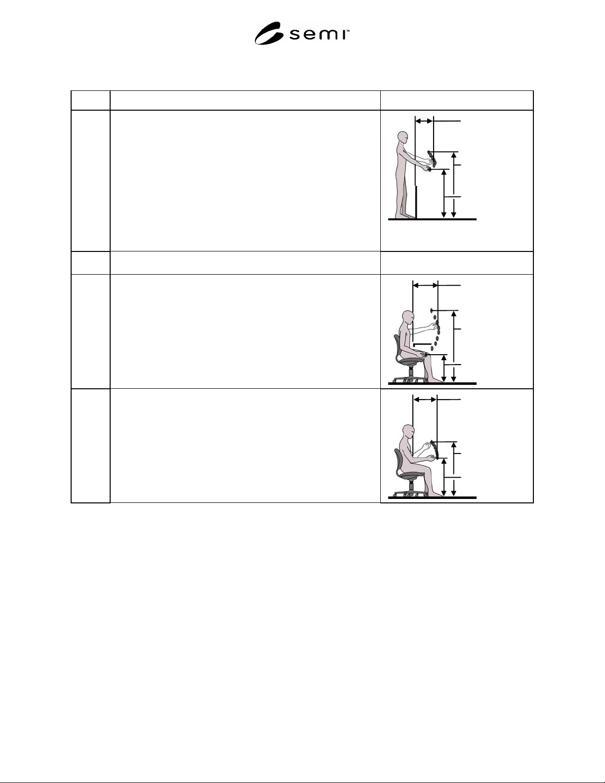
9.1.3 Location of frequently used controls. Maximum reaches are indicated for
various heights. Reaches are measured from the leading edge of the
equipment or obstacle.
Acceptance criteria: controls should not be located above 1270 mm (50
in.) or below 940 mm (37 in.).
NOTE A: Interpolate for intermediate values.
NOTE B: Reach distances should be measured from the leading edge of
the machine housing or obstructions to the center of the
control. Obstructions include keyboard trays, drip trays,
machine load bearing pads and anti-vibration pads.
NOTE C: See Figure 9.1.3 for maximum recommended reaches.
Minimum 940
mm
(37 in.)
Maximum 406
mm
(16 in.)
Maximum 1270
mm
(50 in.)
9.2 Seated station (Note: A seated station is one where a short cylinder
office-style chair is used).
9.2.1 Location of infrequently used and/or critical controls. Maximum reaches
are indicated for various heights. Reaches are measured from the leading
edge of the work surface or obstacle.
Acceptance criteria: Controls should not be located above 1397 mm (55
in.) or below 533 mm (21 in.).
NOTE A: Interpolate for intermediate values.
NOTE B: See Figure 9.2.1 for maximum recommended reaches.
Minimum 533
mm
(21 in.)
Maximum 483
mm
(19 in.)
Maximum 1397
mm
(55 in.)
9.2.2 Location of frequently used controls. Maximum reaches are indicated for
various heights. Reaches are measured from the leading edge of the work
surface or obstacle.
Acceptance criteria: controls should not be located above 1067 mm (42
in.) or below 762 mm (30 in.).
NOTE A: Interpolate for intermediate values.
NOTE B: See Figure 9.2.2 for maximum recommended reaches.
Minimum 762
mm
(30 in.)
Maximum 419
mm
(16.5 in.)
Maximum 1067
mm
(42 in.)
SEMI S8-0705 © SEMI 1995, 2005 57
Section 9: Hand Control Location Figures
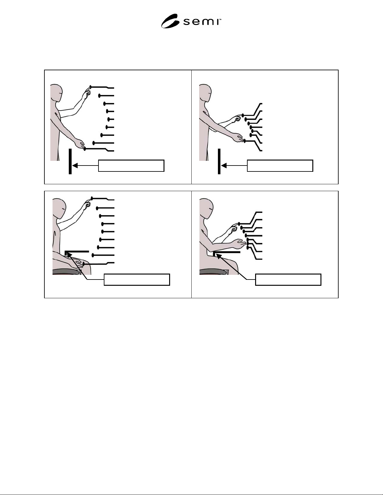
Coordinates given for hand control locations. Height (vertical measurement from standing surface to center of control), Depth
(horizontal measurement from leading edge of work surface to the center of control)
Height and depth of controls
1638, 254 mm
(64.5, 10.0 in.)
1524, 368 mm
(60, 14.5 in.)
1422, 432 mm
(56, 17.0 in.)
1321, 470 mm
(52, 18.5 in.)
1219, 483 mm
(48, 19.0 in.)
1118, 470 mm
(44, 18.5 in.)
1016, 394 mm
(40, 15.5 in.)
914, 292 mm
(36, 11.5 in.)
838, 178 mm
(33, 7.0 in.)
Leading edge of workstation
Figure 9.1.2 Infrequently used standing control reaches
Height and depth of controls
1270, 292 mm
(50, 11.5 in.)
1219, 330 mm
(48,13.0 in.)
1168, 368 mm
(46, 14.5 in.)
1118, 394 mm
(44, 15.5 in.)
1067, 406 mm
(42, 16.0 in.)
1016, 394 mm
(40, 15.5 in.)
940, 318 mm
(37, 12.5 in.)
Leading edge of workstation
Figure 9.1.3 Frequently used standing control reaches
1397, 356 mm
(55, 14.5 in.)
1270, 432 mm
(50, 17.0 in.)
1168, 470 mm
(46, 18.5 in.)
1067, 483 mm
(42, 19.0 in.)
965, 483 mm
(38, 19.0 in.)
864, 470 mm
(34, 18.5 in.)
762, 445 mm
(30, 17.5 in.)
660, 381 mm
(26, 15.0 in.)
533, 254 mm
(21, 10.0 in.)
Leading edge of workstation
Figure 9.2.1 Infrequently used seated control reaches
1067, 330 mm
(42, 13.0 in.)
1016, 368 mm
(40, 14.5 in.)
965, 394 mm
(38, 15.5 in.)
914, 406 mm
(36, 16.0 in.)
864, 419 mm
(34, 16.5 in.)
813, 419 mm
(32, 16.5 in.)
762, 419 mm
(30, 16.5 in.)
Leading edge of workstation
Figure 9.2.2 Frequently used seated control reaches
SEMI S8-0705 © SEMI 1995, 2005 58
Section 10: Workstation Design
Section Indicator Figure
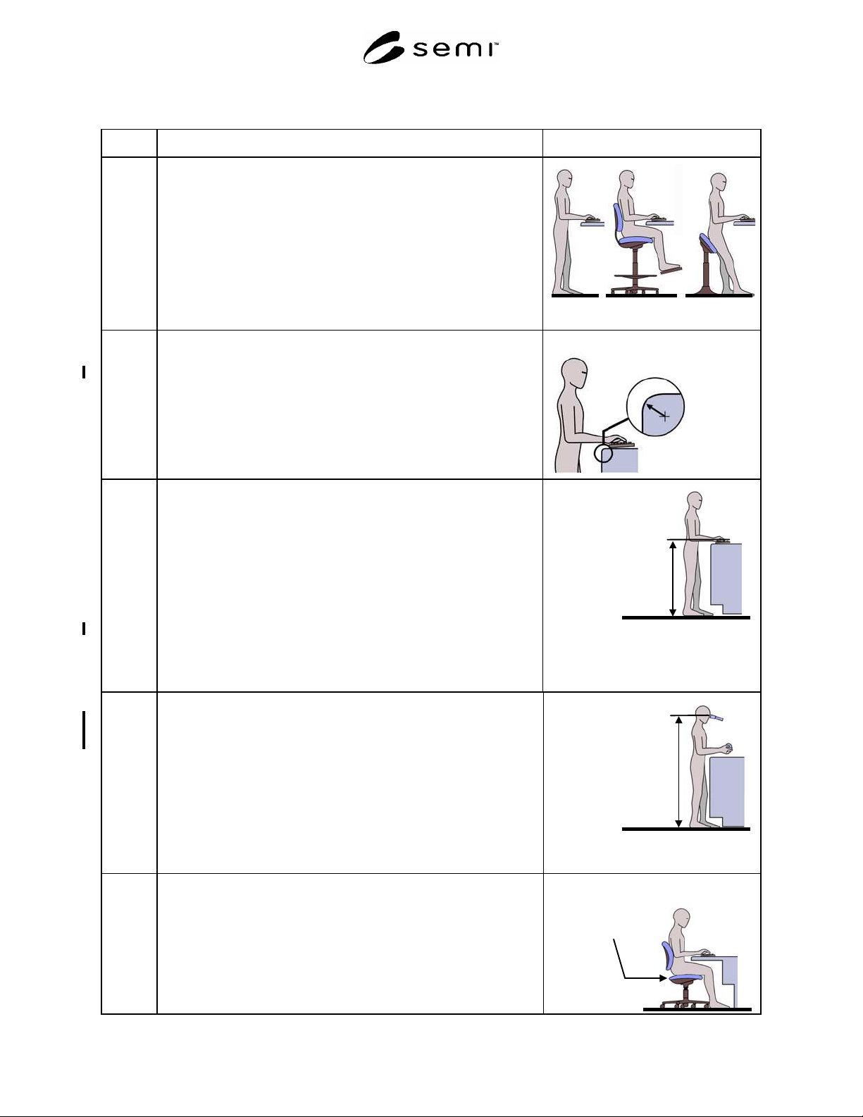
10.1 Standing station (Note A standing station is one where the operator can
assume a standing posture or a seated posture in a tall stool, which places
the operator at approximately the same stature.)
NOTE: If a tall stool, chair or sit/lean stool is used, it is assumed that
the seat is user height-adjustable.
Stand Sit Sit/Lean
10.1.1 Work surface edge radius where the operator can assume a static posture
in contact with the edge.
Acceptance criterion: minimum 6.4 mm (0.25 in.) radius
NOTE: This recommendation applies to both horizontal and vertical
surfaces where the equipment operator can assume a static
posture.
Work surface edge radius
Minimum 6.4 mm
(0.25 in.)
10.1.2 Height of keyboard, trackball, or mouse (to home row, top of ball/mouse).
NOTE: In applications where input devices (keyboard, trackball, or
mouse) are used more like machine controls (intermittent one finger entry
on the keyboard, intermittent short term use of the mouse or trackball)
than for standard typing (continuous use of keyboard for entry of long
character strings, extended use of trackball or mouse in graphical
environment), it is appropriate to use the height and reach locations
described in Section 9, Hand Control Location (standing station).
Acceptance criteria: maximum 1020 mm (40 in.)
minimum 970 mm (38 in.)
NOTE: The home row of a keyboard is the row with the “F” and “J”
typing home keys.
Keyboard, mouse
and trackball height
Maximum 1020 mm
(40 in.)
Minimum 970 mm
(
38 in.
)
10.1.3 Height of microscope eyepieces. Must be adjustable.
Acceptance criterion: Range includes 1270 mm (50 in.) to 1730 mm
(68 in.)
NOTE A: Measured from standing surface to center of the eyepiece.
NOTE B: Both height-adjustable eyepieces and adjustable tables may
be used to meet this recommendation. If a height-adjustable
table is used, the SESC checklist should be used to determine
the appropriate machine load port heights and locations for
displays and controls at the maximum and minimum table
heights.
Maximum 1730 mm
(68 in.)
Minimum 1270 mm
(50 in.)
10.2 Seated station (A seated station where a short cylinder office-style chair is
used.)
NOTE: A height-adjustable chair is assumed.
Height-adjustable,
office style chair