semi合集-English.pdf - 第4848页
SEMI M1-0305 © SEMI 1978, 2005 24 Table 3 Wafer Edge Profile Temp late Coordina tes (See Figure 6) T/3 Wafer Edge Profile Template Point x #1 y #1 A 0.0030 in. 76 m 0.00 in. 0 m B 0.0200 in. 508 m 0.00 in. 0 m C …
SEMI M1-0305 © SEMI 1978, 2005 23
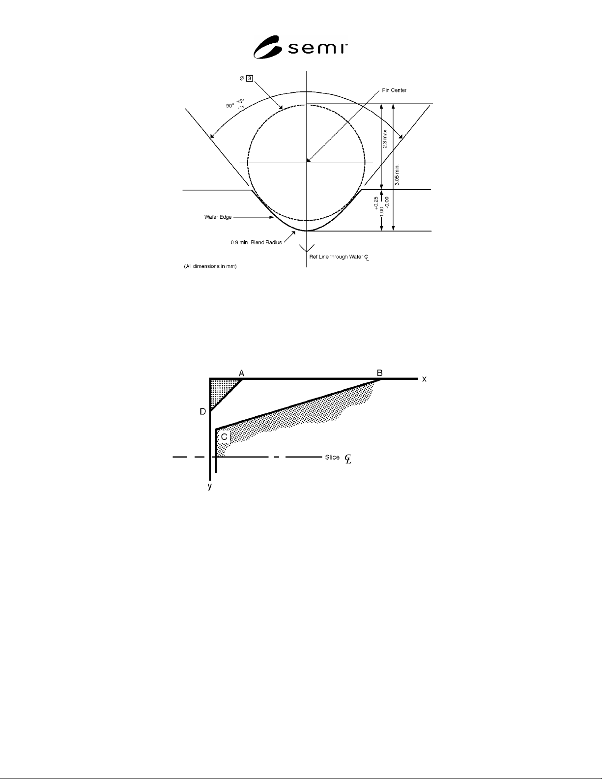
NOTE: The pin shown in the outline on this figure is used to align the notched wafer in a fixture during
use. The pin is also used to reference the notched wafer during testing for notch dimensions and
dimensional tolerances. The notch dimensions shown in the figure assume a 3 mm diameter for this
alignment pin.
Figure 5
Notch Dimensions
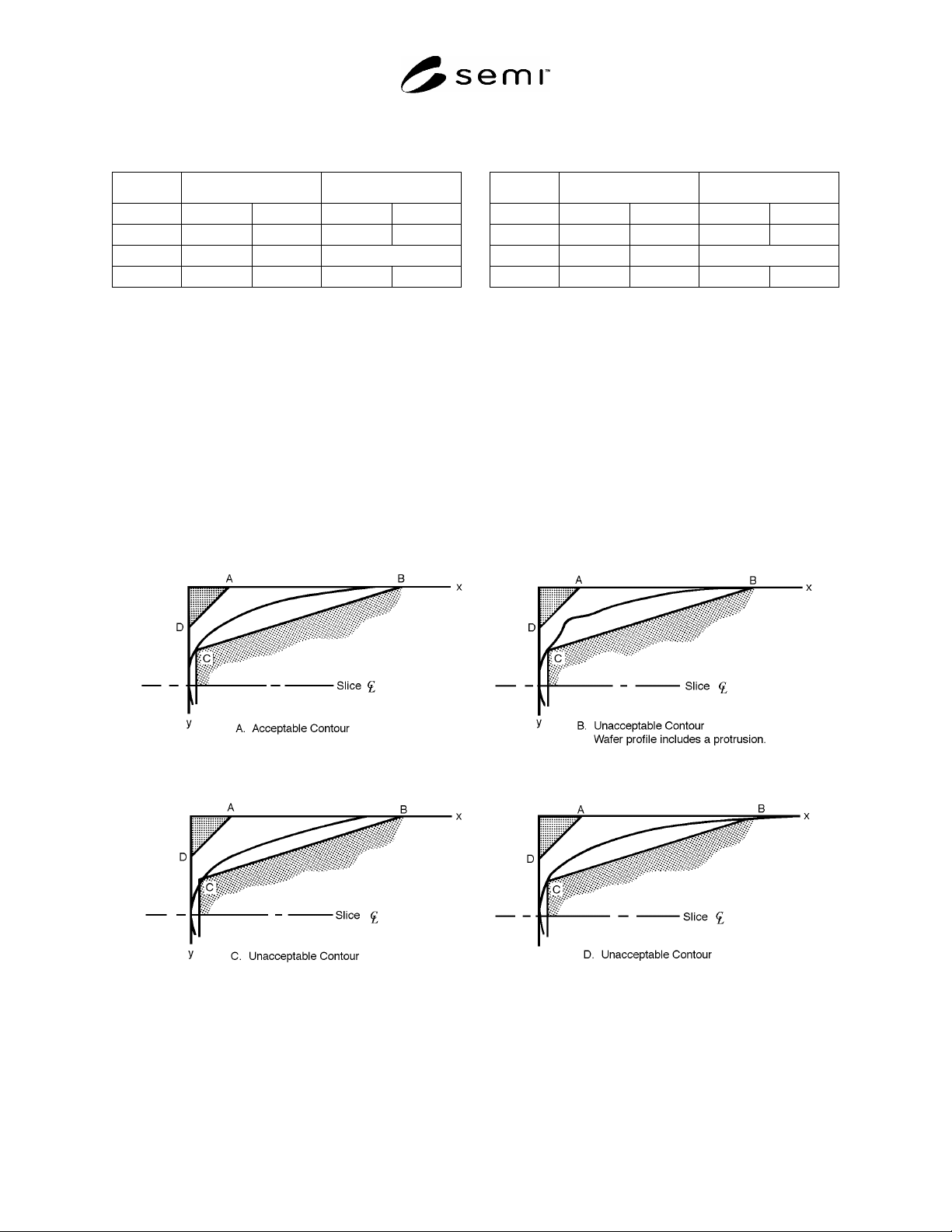
NOTE 1: The figure is not to scale
NOTE 2: Only one-half of the template is shown; the wafer surface is aligned with the x-axis, and the outermost radial portion of
the edge contour is aligned with the y-axis. The template in this figure is not intended for use in measuring wafer thickness.
NOTE 3: Constant radius profile with blended, tangential front and back surface intercepts is preferred for ease of manufacture
and reduced particle and chip generation.
NOTE 4: The x- and y-axes in this template do not correspond with the x- and y-axes in the wafer coordinate system defined in
SEMI M20.
Figure 6
SEMI Wafer Edge Profile Template
SEMI M1-0305 © SEMI 1978, 2005 24
Table 3 Wafer Edge Profile Template Coordinates (See Figure 6)
T/3 Wafer Edge Profile Template
Point x
#1
y
#1
A 0.0030 in.
76 m
0.00 in.
0 m
B 0.0200 in.
508 m
0.00 in.
0 m
C 0.0020 in.
50 m
T/3
#2
D 0.00 in.
0 m
0.0030 in.
76 m
T/4 Wafer Edge Profile Template
Point x
#1
y
#1
A 0.0047 in.
120 m
0.00 in.
0 m
B 0.0200 in.
508 m
0.00 in.
0 m
C 0.0040 in.
100 m
T/4
#2
D 0.00 in.
0 m
0.0020 in.
50 m
#1
For referee purposes, U.S. Customary units are to be used for 2 and 3 in. diameter wafers SI units are to be used for all other wafers.
#2
For the value of this coordinate, see the specifications for the appropriate wafer category in Tables 4 through 9.
6.6.2.2 The coordinates for the two templates are given in Table 3. Note that this coordinate system differs from
that in SEMI M20 in that the origin is at the wafer edge instead of the wafer center and the y-axis is positive in the
downward direction toward the wafer median plane instead of being in the plane of the wafer surface. If the
nominal edge exclusion, EE, is 1 mm or greater, the edge profile will not extend into the fixed quality area.
6.6.2.3 When the wafer is aligned with the Template so that the x-axis of the template is coincident with the wafer
surface and the y-axis of the template is tangent with the outermost radial portion of the profile, the wafer edge
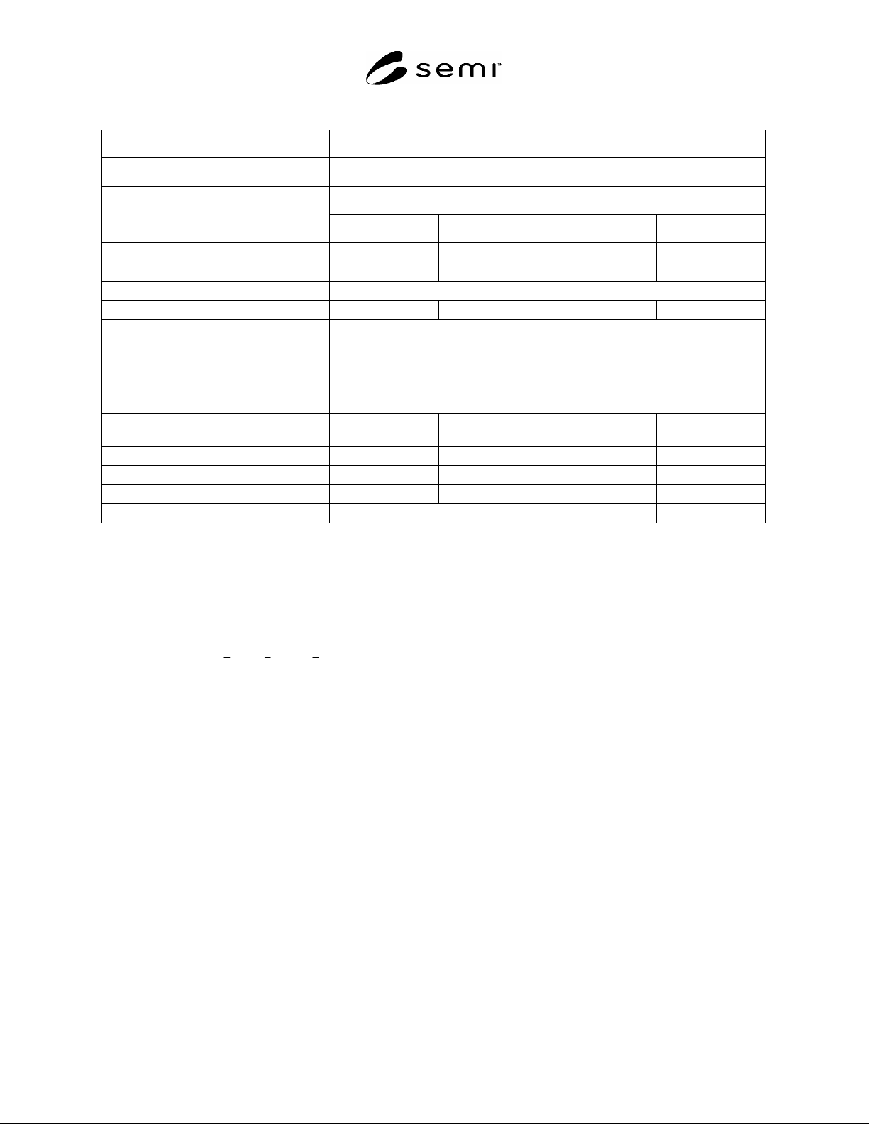
profile must be contained within the clear region of the template. (See Figure 7 for examples of acceptable and
unacceptable edge profiles.)
6.6.2.4 No sharp points or protrusions are permitted anywhere on the wafer edge profile.
6.6.2.5 Cosmetic attributes of the edge profile are not covered by this specification. They shall be agreed upon
between supplier and customer.
Figure 7
Examples of Acceptable and Unacceptable Wafer Edge Profiles
SEMI M1-0305 © SEMI 1978, 2005 25
Table 4 Dimensional Characteristics of 2 in. and 3 in. Polished Monocrystalline Silicon Wafers
#1
Previous SEMI Reference: SEMI M1.1 SEMI M1.2
Wafer Category: 1.1 1.2
2 in. Wafers 3 in. Wafers
Property
U.S. Customary
#2
Metric (SI
#2
U.S. Customary
#2
Metric (SI)
#2
2-6.1 Diameter
2.000 0.015 in. 50.80 0.38 mm 3.000 0.025 in. 76.20 0.63 mm
2-6.2 Primary Flat Length
0.625 0.065 in. 15.88 1.65 mm 0.875 0.125 in. 22.22 3.17 mm
2-6.3 Primary Flat Orientation
#3
{110} 1
2-6.4 Secondary Flat Length
0.315 0.065 in. 8.00 1.65 mm 0.440 0.060 in. 11.18 1.52 mm
2-6.5 Secondary Flat Location
(See Figure 4)
{111} p-type
{100} p-type
{111} n-type
{100} n-type
No secondary flat
90 5 clockwise from primary flat (
= 180 5)
45 5 clockwise from primary flat (
= 225 5)
180 5 from primary flat (
= 90 5)
2.6.6 Edge Profile Coordinate, C
y
(T/3 Template, see Table 3)
0.0037 in.
93 m
0.0050 in.
127 m
2-6.7 Thickness, Center Point
0.0110 0.0010 in. 279 25 m 0.0150 0.0010 in. 381 25 m
2-6.8 Total Thickness Variation, Max. 0.0005 in.
12 m
0.0010 in.
25 m
2-6.9 Bow, Max. 0.0015 in.
38 m
0.0016 in.
40 m
2-6.10 Warp, Max. not specified 0.0016 in.
40 m
#1
Note that these specifications were originated in the United States. Care should be taken in applying this configuration to specific applications
(see ¶6.6.3).
#2
For referee purposes, U.S. Customary units apply. To ensure that product shipped is within specification, any conversion to metric (SI)
equivalents should be done following the maximum-minimum convention in which the minimum values are rounded-up and the maximum values
are rounded-down to ensure that the equivalent range is always inside the referee range. If the metric (SI) equivalents are used for incoming
inspection, minimum values should be rounded-down and maximum values rounded-up to avoid rejection of material that is within the
specification when measured by the referee system of units. CAUTION: The significance of the rightmost digit may vary, depending on the
quantity being measured and the precision of the test procedure. Refer to the relevant test method for precision data which can be used to
construct appropriate guard bands.
#3
For )111( wafers, the
),011( ),101( , and )011( planes are the equivalent, allowable (110) planes. For (100) wafers, the allowable equivalent
)110( planes are
),101( ),011( ),110( and ).110(