semi合集-English.pdf - 第1002页
SEMI E135-0704 © SEMI 2004 7 Tim e D el ay NOTE: These data are for conditions where the r equested power went from 0% to 100% of the full power of the RF Generator being tested. Figure 5 Example of Digital Oscillosco pe…
SEMI E135-0704 © SEMI 2004 6
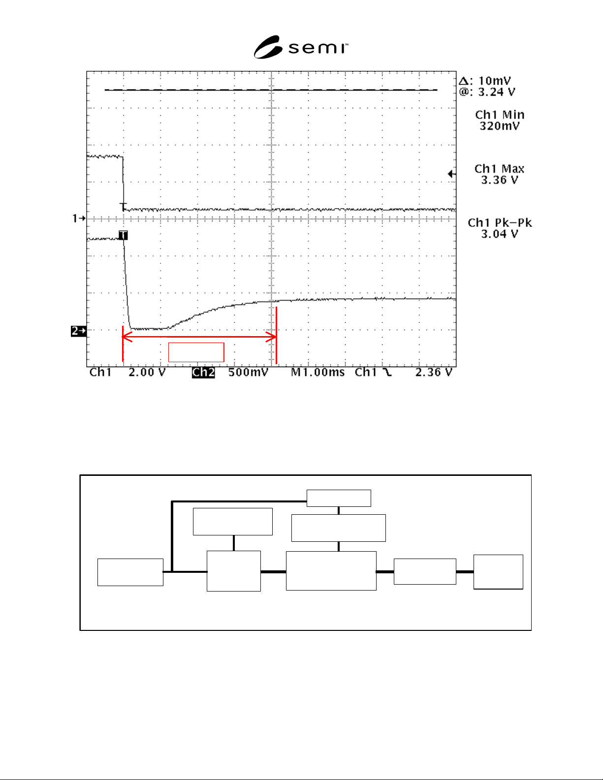
NOTE: These data are for conditions where the requested power went from 33% to 3% of the full power of the RF Generator
being tested.
Figure 3
Example of Digital Oscilloscope Data that Shows the Transient Response of the RF Output Power (Lower
Trace) Due to a Change in Set Point Signal (Upper Trace)
RF Signal Sample
r
D
irectional or
N
ondirectional
RF Powe
r
Mete
r
High-Power
RF Dummy
Load
R
F
Generator
(
DUT
)
RF Rectifier
/
Diode Detecto
r
Digital Scope
RF Enable
Signal Generato
r
RF Set-Point
/
Signal Generato
r
NOTE: If cable assemblies are used between the output of the RF Generator (DUT) and the High-Power Dummy Load, they shall
have the same nominal impedance as the DUT and shall have a power handling capability that is consistent with the maximum
output power of the RF Generator (DUT).
Figure 4
Schematic of the Test Setup for the Measuring the Transient Response of the RF Generator (DUT) as a
Function of a Change in the RF Enable Signal
SEMI E135-0704 © SEMI 2004 7
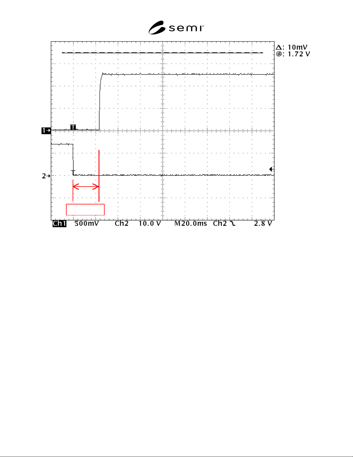
Time Delay
NOTE: These data are for conditions where the requested power went from 0% to 100% of the full power of the RF Generator
being tested.
Figure 5
Example of Digital Oscilloscope Data that Shows the Transient Response and Time Delay of the RF Output
Power (Upper Trace) Due to a Change in the RF Enable Signal (Lower Trace)
NOTICE: SEMI makes no warranties or representations as to the suitability of the standards set forth herein for any
particular application. The determination of the suitability of the standard is solely the responsibility of the user.
Users are cautioned to refer to manufacturer's instructions, product labels, product data sheets, and other relevant
literature, respecting any materials or equipment mentioned herein. These standards are subject to change without
notice.
By publication of this standard, Semiconductor Equipment and Materials International (SEMI) takes no position
respecting the validity of any patent rights or copyrights asserted in connection with any items mentioned in this
standard. Users of this standard are expressly advised that determination of any such patent rights or copyrights, and
the risk of infringement of such rights are entirely their own responsibility.
Copyright by SEMI® (Semiconductor Equipment and Materials
International), 3081 Zanker Road, San Jose, CA 95134. Reproduction o
f
the contents in whole or in part is forbidden without express written
consent of SEMI.

SEMI E136-1104 © SEMI 2004 1
SEMI E136-1104
TEST METHOD FOR DETERMINING THE OUTPUT POWER OF RF
GENERATORS USED IN SEMICONDUCTOR PROCESSING
EQUIPMENT RF POWER DELIVERY SYSTEMS
This test method was technically approved by the Global Metrics Committee and is the direct responsibility
of the North American Metrics Committee. Current edition approved by the North American Regional
Standards Committee on July 11, 2004. Initially available at www.semi.org September 2004; to be published
November 2004.
1 Purpose
1.1 The purpose of this test method is to provide an
accurate method for measuring the output power of RF
generators used in RF power delivery systems for
semiconductor processing equipment to support SEMI
E113.
2 Scope
2.1 This test method specifies the testing procedures
and test equipment required for determining the true
output power (i.e., heating power) output of RF
generators. This test method uses a calorimetric power
meter, which was calibrated previously using precise
DC substitution techniques as a reference standard.
2.2 The primary focus for this test method is
semiconductor processing equipment including, but not
limited to, the following equipment types:
Dry etch equipment, and
Film deposition equipment (CVD and PVD).
NOTICE: This standard does not purport to address
safety issues, if any, associated with its use. It is the
responsibility of the users of this standard to establish
appropriate safety and health practices and determine
the applicability of regulatory or other limitations prior
to use.
3 Limitations
3.1 This test method is meant to provide a general
means of measuring the true output power of RF
generators operating over a wide range of frequency
and power. Limitations in the frequency and power
coverage of this method are determined by the
individual system components chosen.
3.2 This test method assumes that the transmission
system characteristic impedance is 50 .
3.3 International, national, and local codes, regulations
and laws should be consulted to ensure that the
equipment and procedures meet regulatory
requirements in each location.
3.4 Certain safety issues associated with the test
procedures themselves are mentioned as a reminder that
safety procedures are necessary for safe conduct of the
test.
3.5 This standard does not address any safety or
performance issues related to RF emissions or electrical
codes (e.g., Underwriter’s Laboratory, Inc. (UL), the
National Electrical Code (NEC
), Federal
Communications Commission (FCC)). It is the
responsibility of the users of this standard to conform to
the appropriate local codes and regulations as applied to
this type of equipment, some of which are covered by
referenced documents.
4 Referenced Standards
4.1 SEMI Standards
SEMI E113 — Specification for Semiconductor
Processing Equipment RF Power Delivery Systems
SEMI E114 — Test Method for RF Cable Assemblies
Used in Semiconductor Processing Equipment RF
Power Delivery Systems
NOTICE: Unless otherwise indicated, all documents
cited shall be the latest published versions.
5 Terminology
5.1 Abbreviations and Acronyms
5.1.1 AC — Alternating Current
5.1.2 CVD — Chemical Vapor Deposition
5.1.3 DC — Direct Current
5.1.4 NIST — National Institute for Standards and
Technology
5.1.5 PVD — Physical Vapor Deposition
5.1.6 RF — Radio Frequency
5.1.7 VSWR — Voltage Standing Wave Ratio
5.2 Definitions
5.2.1 cable assembly — the section of cable
(transmission line), including the connectors, used to