semi合集-English.pdf - 第2010页
SEMI E54.7-0999 © SEMI 1999 4 services, and creating , defining a nd communicating object attributes in an applicatio n dependent format. The device shall comply with the object messaging an d object model s pecification…
SEMI E54.7-0999 © SEMI 19993
of the Reference Model. The high level protocol
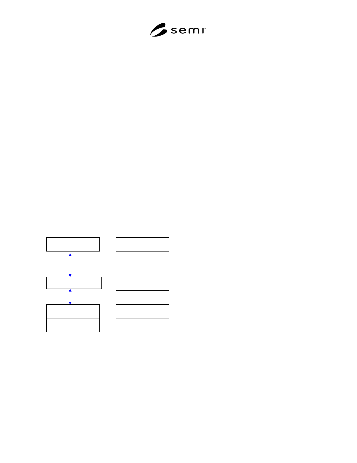
architecture is shown in Figure 1.
6.1.1 Note that Figure 1 represents a conceptual view
of the device architecture. Conforming implementations
must implement the services defined in this
specification at each layer and must appear (from the
network) to have implemented this architecture,
however an internal modular partitioning is not
required. Implementations may sacrifice modularity in
order to achieve high performance.
6.1.2 The Seriplex physical layer is fully specified in
the Seriplex Standard Specification. There are guideline
specified for the topology of the bus cable, length of
bus cable and number of bus nodes within the system.
Typical configurations include: Daisy Chain,
Trunk/Dropline, Tree, Loop, Star and Combinations of
the above. Reference guidelines are specified for the
cable length and node limits determined by a system’s
Clock rate and total data line capacity within a system.
Bus Power Supply provides power for the Seriplex bus
itself – that is, for the Seriplex bus communication
circuitry within each bus device. The bus power supply
normally provides a 24 VDC source for the bus. In
general, the bus supply does not provide power to
monitoring and control devices.
Application Layer
Data Link
Physical Layer
Layered View of Seriplex
Application Layer
Presentation Layer
Session Layer
Transport Layer
N
etwork Layer
Data Link Layer
Physical Layer
OSI Reference Model
Transport Layer
Figure 1
Layered View of Seriplex
6.1.3 At the data link layer, the Seriplex standard
messaging specification defines a carrier sense multiple
access mechanism for media access control that
supports non-destructive collision resolution and sends
frames reliably.
6.1.4 The application layer is specified in the Seriplex
standard specification and provides for the definition of
Seriplex applications as a collection of addressable
objects. A subset of these objects may be addressed
over the network (as defined by the implementation).
6.1.5 In the remainder of this section the protocol
structure is described in more detail in terms of the OSI
seven layer reference model, the object model
environment and network management specifications.
6.2 Physical Layer — The device shall comply with
the Seriplex physical layer specification (contained in
Seriplex standard specification). This includes physical
signaling (levels and data rates), transceivers, node
isolation, media topology, cable specifications, network
connectors and taps, and power considerations (load
limits, system tolerances, and power supply options).
6.3 Data Link Layer — The device shall comply with
the Seriplex standard specification for the Data Link
Layer. This includes the media access control
mechanism and the logical link control mechanism.
Addressing is currently limited to 8 bits of source
address and 8 bits of destination address. Bitwise
arbitration is used to gain access to the network in cases
where multiple nodes contend for the same message
bandwidth.
6.4 Network Layer — There is no distinct network
layer.
6.5 Transport (Messaging) Layer — The device shall
comply with the Seriplex standard specification for the
Messaging Layer. The messaging layer provides
transparent transfer of data between objects in
application-entities. Some of the functionality, of this
layer is implemented in the Application Layer. Specific
functions include: segmentation/re-assembly (fragmen-
tation) for full message delivery.
6.6 Session Layer — There is no distinct session layer.
6.7 Presentation Layer — There is no distinct
presentation layer. Object addressing and data
presentation in Seriplex messages are specified as part
of the Seriplex object definitions and object attribute
and service communication protocol.
6.8 Application Layer — The device shall comply
with the Seriplex application layer specification for
defining and addressing objects, including their
attributes and services, and enabling specified network
behavior. The device shall comply with the object
messaging and object model specifications included in
the Seriplex standard specification. In addition the
device shall comply with the object specifications
defined in Section 7 of this document.
6.8.1 Object Models — The Seriplex protocol has
been enhanced to provide an object-oriented
specification for creating, defining and addressing
objects explicitly, including their attributes and
SEMI E54.7-0999 © SEMI 1999 4
services, and creating, defining and communicating
object attributes in an application dependent format.
The device shall comply with the object messaging and
object model specifications included in the Seriplex
standard specification documentation. In addition the
device shall comply with the object specifications
defined in Section 7 of this document.
6.8.2 Alternate Method for the Communication
Transmission of Attributes — In order to take
advantage of the Seriplex network’s speed and
deterministic characteristics, the Seriplex Standard
Specification details a mechanism of transmitting data
over the network by assigning, in advance, a sequence
of serial frames to be used collectively to deliver
specific sensor and/or actuator attribute data. This
mechanism can be utilized as an alternative to the
object messaging specification of the Seriplex Standard
Specification to implement the behavior associated with
the GetAttribute and SetAttribute services detailed in
Section 7. This mechanism may be used to provide an
efficient and optimum implementation of data
transmission over the network.
6.9 Network Management — The device shall comply
with the Seriplex network management specifications
detailed in the Seriplex Standard Specification (e.g.,
physical layer bit rate, master/slave and peer-to-peer
network management, etc.). No (additional) network
management functions are specified in this document.
7 Required Object Types
7.1 At this time, the Seriplex Standard Specification
does not require any specific objects to exist in a
Seriplex device in order to be a compliant Seriplex
device. The Seriplex Standard Specification will be
extended to identify and describe objects (i.e. classes)
that must exist in devices that are to be interoperable
and interchangeable on a Seriplex SEMI compliant
SAN network.
7.1.1 The Common Device Model specification
identifies two objects (namely the Device Manager
(DM) and Sensor Actuator Controller (SAC) objects)
that must exist in all SEMI compliant SAN devices.
The required object types for a SEMI compliant SAN
device utilizing the network communication
specification described herein, necessarily comprises
the union of the above two requirements.
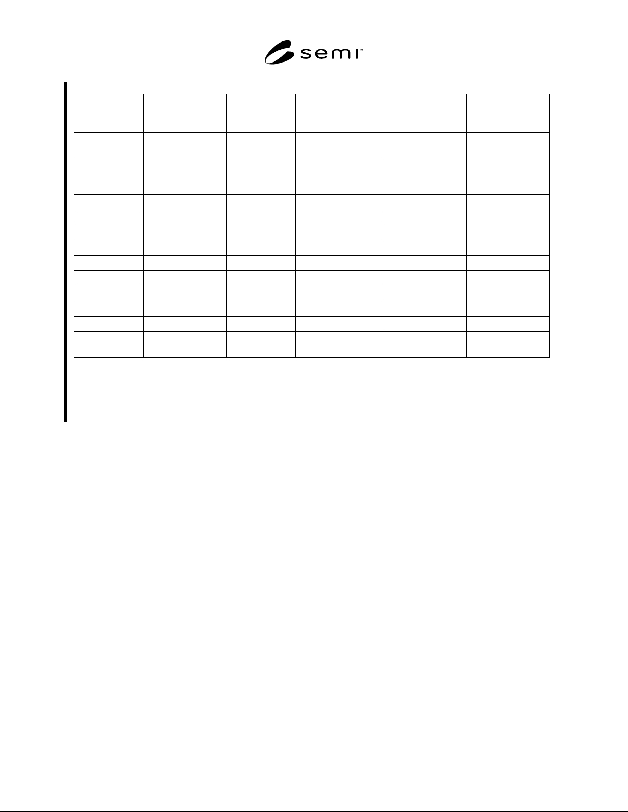
7.1.2 A list of required and optional object types is
given in Table 2. Additional objects that are specified
in a particular SDM are given identifiers in that SDM
specification; Seriplex specific presentation information
for these identifiers is given in Section 9 of this
document.
7.1.3 An embodiment of a specific device type,
represented as an aggregation of the object types listed
in Table 2, that is compliant with both the CDM
specification and the Seriplex specification, is a
candidate for a SEMI SDM as well as a Seriplex device
definition. Conversely, all SEMI SDM’s and Seriplex
device definitions specified for operation over a SEMI
compliant Seriplex network must be an aggregation of
the object types listed in Table 2, and be compliant with
both the CDM specification and the Seriplex standard
specification.
7.1.4 In the following sections the presentation to the
network of object addressing, object attributes, and
object services for each of the object types listed in
Table 2 is described in detail. Refer to the CDM
standard to determine if the object instance attribute and
service is specified as required or optional. Unless
otherwise noted, all attributes and services described
are instance level attributes (as opposed to class level
attributes). A class level attribute and service is
accessed as instance number zero.
7.1.5 Note that the formats of object attributes and
services are detailed in the CDM document; the
presentation of object attributes and services to the
Seriplex network is detailed in the tables contained in
the following sub-sections and in the Seriplex standard
specification.
7.2 Device Manager (DM) Object –– The DM object
is the device component responsible for managing and
consolidating the device operation. Each device must
support one (and only one) DM object. The DM object
as well as its common required and optional attributes,
services and behavior are described in the CDM
standard. The presentation of object instance attributes
and services to the Seriplex network shall be as
indicated in Table 3.
7.2.1 Note that the formats of DM object attributes are
detailed in the CDM document; the presentation of DM
object attributes to the Seriplex network is detailed in
Table 3 and the Seriplex standard specification; the
format of DM object services is detailed in the CDM
document and the Seriplex standard specification; and
the presentation of the DM object services is detailed in
Table 3 and the Seriplex standard specification.
SEMI E54.7-0999 © SEMI 19995
Table 2 Required and Optional Object Types
Object Name Seriplex Class
ID/Instance ID
(See Note 1)
CDM Tag
(See Note 2)
Required by Seriplex
(See Note 1)
Required by CDM
(See Note 2)
Required by NCS
Device
Manager
1/1 DmI0 No Yes Yes
Sensor/
Actuator/
Controller
2/1 SacI0 No Yes Yes
Assembly 3/1 through i Asm No No No
Local Link 4/1 through j Lnk No No No
Sensor – AI 33/1 through k Sai No No No
Sensor – EI 34/1 through l Sei No No No
Sensor – BI 35/1 through m Sbi No No No
Actuator – AO 36/1 through n Aao No No No
Actuator – EO 37/1 through o Aeo No No No
Actuator – BO 38/1 through p Abo No No No
Controller 39/1 through q Ca No No No
Application
Objects
129 through x/
1 through r
(See Note 3) No No No
NOTE 1: See Seriplex specification for further information; values are decimal; ‘i’, ‘j’, ‘k’, ‘l’, ‘m’, ‘n’, ‘o’, ‘p’, ‘q’ and ‘r’
represent arbitrary numbers (greater than or equal to 1) indicating that more than one instance may be supported. ‘x’ is a number
greater than or equal to 129 indicating that one or more application object classes may be supported.
NOTE 2: See CDM specification for further information.
NOTE 3: Application Dependent objects as specified in SDM.