semi合集-English.pdf - 第4660页
SEMI C3.40-10 00 © SEMI 1989 , 2000 4 5.6.2.3 Flu o ride ion selective electrod e 5.6.2.4 Mag netic stir bars (PTFE coat e d ) 5.6.2.5 Magnetic stirre r 5.6.2.6 Plastic beak ers (See note 5) 5.6.2.7 P T FE bubblers 5.6.2…
SEMI C3.40-1000 © SEMI 1989, 20003
5.3.4.2 Purge the sampling lines with the standard for
at least one minute.
5.3.4.3 Pressurize the sampling lines to 5 psig.
5.3.4.4 Inject the standard into the gas chromatograph,
and start the scan. Record the retention times and peak
areas. Order of elution for the above mentioned
standard is carbon tetrafluoride, trifluoromethane,
hexafluoroethane, chlorotrifluoromethane, and
dichlorodifluoromethane.
5.3.4.5 Inject the sample to be tested in the same
manner as the calibration standard.
5.3.4.6 Repeat 5.3.4.1–5.3.4.4.
5.3.4.7 Compare the average peak areas of the
calibration standard to those of the carbon tetrafluoride
sample being tested. Calculate the concentration of each
of the impurities using the formula below. The results
may not exceed the specifications in Section 2 of this
Standard.
Sample Peak Area
Standard Peak Area
×
Concentration
of Standard
=
Concentration
of Sample
5.4 Sulfur Hexafluoride — This procedure is for the
determination of sulfur hexafluoride in carbon
tetrafluoride using a gas chromatograph with a thermal
conductivity detector. (See Figure 2.)
5.4.1 Detection Limit — 0.5 ppm.
5.4.2 Instrument Parameters
5.4.2.1 Column: Super Q, 80/100 mesh, 4.9 m (16 ft)
by 1.75 mm (1/16 in) ID, 3.2 mm (1/8 in) OD, ss or
equivalent.
5.4.2.2 Carrier Flow: 19 mL/min helium.
5.4.2.3 Temperatures:
Detector 100°C
Oven 70°C
Gas sampling valve 70°C
5.4.2.4 Sample Volume: 1 mL.
5.4.3 Calibration Standard — 1 ppm sulfur
hexafluoride, balance helium.
5.4.4 Operating Procedures
5.4.4.1 Inject the calibration standard into the column
using a gas sampling valve. Record retention time and
peak area.
5.4.4.2 Inject the sample to be tested in the same
manner as the calibration standard. Record the retention
times and peak areas.
5.4.4.3 Repeat 5.4.4.1.
5.4.4.4 Compare the average peak areas of the
calibration standard to those of the carbon tetrafluoride
sample being tested. Calculate the concentration of
sulfur hexafluoride using the formula below. The result
may not exceed the specification in Section 2 of this
Standard.
Sample Peak Area
Standard Peak Area
×
Concentration
of Standard
=
Concentration
of Sample
5.5 Water — This procedure is for the determination
of trace moisture (water) in carbon tetrafluoride using a
continuous flowing electrolytic hygrometer.
5.5.1 Detection Limit — 1.0 ppm (vol/vol) or -76°C
(-105°F).
5.5.2 Flow Requirements — Set the sample pressure
and flow rate in accordance with the instrument
manufacturer’s instructions.
5.5.3 Operation Check — Check the electrolytic
hygrometer periodically. A gas, containing a known
amount of water, should be passed through the
hygrometer. Agreement between the electrolytic
hygrometer and the moisture standard should be within
their relative accuracies.
5.5.4 Operating Procedure
5.5.4.1 Obtain a continuous flow sample of gas, from
the CF
4
source, using a clean, passivated stainless steel
line which has been purged dry after exposure to
ambient moisture. (See Notes 3 and 4.)
5.5.4.2 After prepurging with a dry gas, allow the
sample gas to flow through the sampling system and the
electrolytic moisture analyzer until a stable reading is
obtained. The result may not exceed the specification in
Section 2 of this standard.
5.6 Hydrolyzable Fluorides as HF — This procedure
is for the determination of hydrolyzable fluorides in
carbon tetrafluoride using fluoride ion selective
electrode.
5.6.1 Detection Limit — Detection limits should be
checked for any new implementation of a method.
Detection limits below 0.1 ppm have been determined
with this method. Detection limits can be improved by
increasing the volume of gas sampled.
5.6.2 Equipment
5.6.2.1 mV meter (0.1 mV scale)
5.6.2.2 Reference electrode (single junction type)
SEMI C3.40-1000 © SEMI 1989, 2000 4
5.6.2.3 Fluoride ion selective electrode
5.6.2.4 Magnetic stir bars (PTFE coated)
5.6.2.5 Magnetic stirrer
5.6.2.6 Plastic beakers (See note 5)
5.6.2.7 PTFE bubblers
5.6.2.8 1000 ml and 100 ml plastic volumetric flasks
(See note 5)
5.6.2.9 0.2 ml and 1 ml plastic volumetric pipettes
(See note 5)
5.6.2.10 Flow controller or flowmeter (0-1000 sccm
CF
4
)
5.6.3 Reagents
5.6.3.1 Distilled or deionized water
5.6.3.2 5 N sodium hydroxide
5.6.3.3 0.2 N sodium hydroxide
5.6.3.4 Glacial acetic acid
5.6.3.5 Buffer Solution — To 500 ml distilled or
deionized water in a 1000 ml volumetric flask, add 57
ml glacial acetic acid and 58 g of sodium chloride.
Adjust the pH to between 5.0–5.5 with 5 M sodium
hydroxide. Cool to room temperature. Dilute to one
liter with distilled or deionized water.
5.6.4 Calibration Standard — Sodium fluoride
standard (10
-3
M F
-
in water, freshly prepared)
5.6.5 Operating Procedure
5.6.5.1 Prepare working standard by adding 100 ml
10
-3
M F
-
to 100 ml buffer solution.
5.6.5.2 Prepare a blank containing 50.0 ml 0.2 N
NaOH and 50.0 ml buffer solution in a plastic beaker.
5.6.5.3 While stirring blank gently, record mV reading
from the blank once reading is stable.
5.6.5.4 Successively add increments of working
standard to the blank to generate a calibration curve.
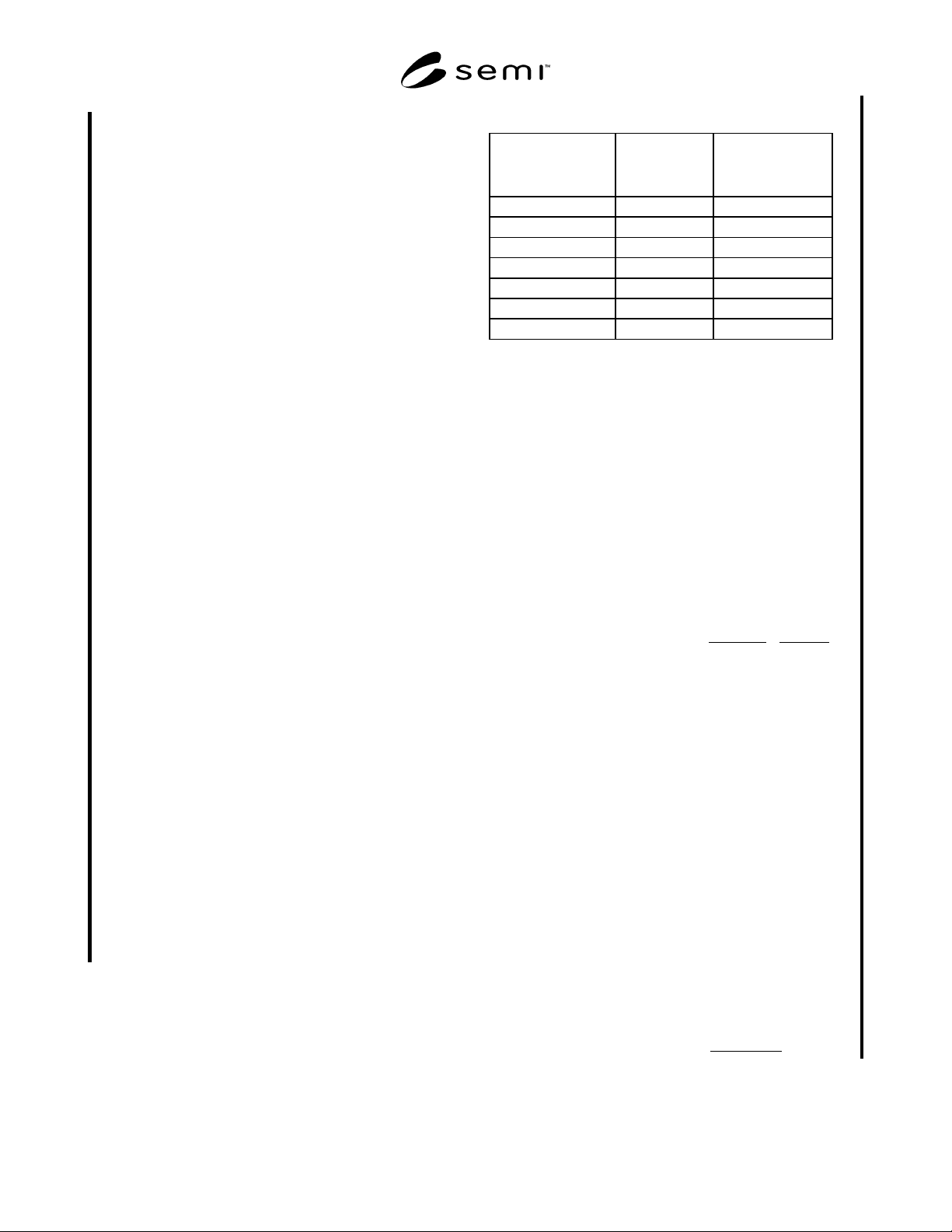
Record stable mV reading after each addition. Table 1
shows recommended increments and resultant
concentrations.
Table 1 Calibration Concentrations
Added volume of
Working Standard
(ml)
Total Volume
(ml)
Resulting F-
Concentration
(M)
0.2 100.2 1.0 x10
-6
0.2 100.4 2.0 x10
-6
0.4 100.8 4.0 x10
-6
0.4 101.2 5.9 x10
-6
0.8 102.0 9.8 x10
-6
1.0 103.0 1.5 x 10
-5
2.0 105.0 2.4 x 10
-5
5.6.5.5 Put 50 ml 0.2 N NaOH into each of two
bubblers connected in series
5.6.5.6 Establish a flow of < 1000 sccm of CF
4
through the bubblers using a suitable flow controller or
flowmeter.
5.6.5.7 Sample approximately 15 liters of CF
4
.
Record flowrate and time of sampling to determine total
volume sampled (flowrate x time). A wet test meter
can also be used to measure total volume. The amount
of gas sample must be the volume at STP. If the
flowmeter or wet test meter is not reference to 0º and
760 torr, use the formula below to correct sample
volume.
K 273
273 T
P
Torr 760
Liters Measured STPat Liters
+
××=
P: Pressure of sampled gas (mm Hg)
T: Temperature of sampled gas or reference
temperature of the flow controller or meter in ºC.
5.6.5.8 Transfer contents of each bubbler to individual
100 ml volumetric flasks and add 50 ml Buffer solution
to each. Then, if necessary, add deionized or distilled
water to bring the volume up to 100 ml.
5.6.5.9
Transfer contents to a plastic beaker
5.6.5.10 While stirring, measure and record mV
readings for each sample.
5.6.5.11 Determine F
-
concentration in solution using
calibration curve generated in section 5.6.5.4.
5.6.5.12 Calculate gas phase hydrolyzable fluoride
concentration using the equation below. Note: the
equation assumes the hydrolyzable fluoride is hydrogen
fluoride.
6
y
10
Vs
l/mole 22.4
0.11 C )(ppm HF Phase Gas ×××=
SEMI C3.40-1000 © SEMI 1989, 20005
C: Measured hydrolyzable fluoride concentration (M)
determined in section 5.6.5.11
Vs: Volume of CF
4
sampled (liters at STP)
5.6.5.13 The HF concentration of the second bubbler
should be insignificant compared to the first bubbler. If
significant HF levels are found in the second bubbler,
resample with a lower flowrate.
5.7
Notes
Note 1: Introduce the calibration standard as many
times as necessary to achieve the desired precision.
Note 2: All gases used in the analysis of the sample
should not contain more than 10% of the specified
value of the component of interest, unless otherwise
stated.
Note 3: A passivation procedure is described in the
Metals Handbook, 10th ed., Vol. 2, American Society
for Metals, Metals Park, OH.
Note 4: The sampling system and hygrometer must be
designed to operate at the sample pressure, or the
sample pressure must be reduced, by a regulator with a
diaphragm of stainless steel or other suitable material,
to accommodate the pressure restrictions of the
hygrometer.
Note 5: Polytetrafluoroethlyene, polymethylpentene
and polypropylene are suitable plastic materials.
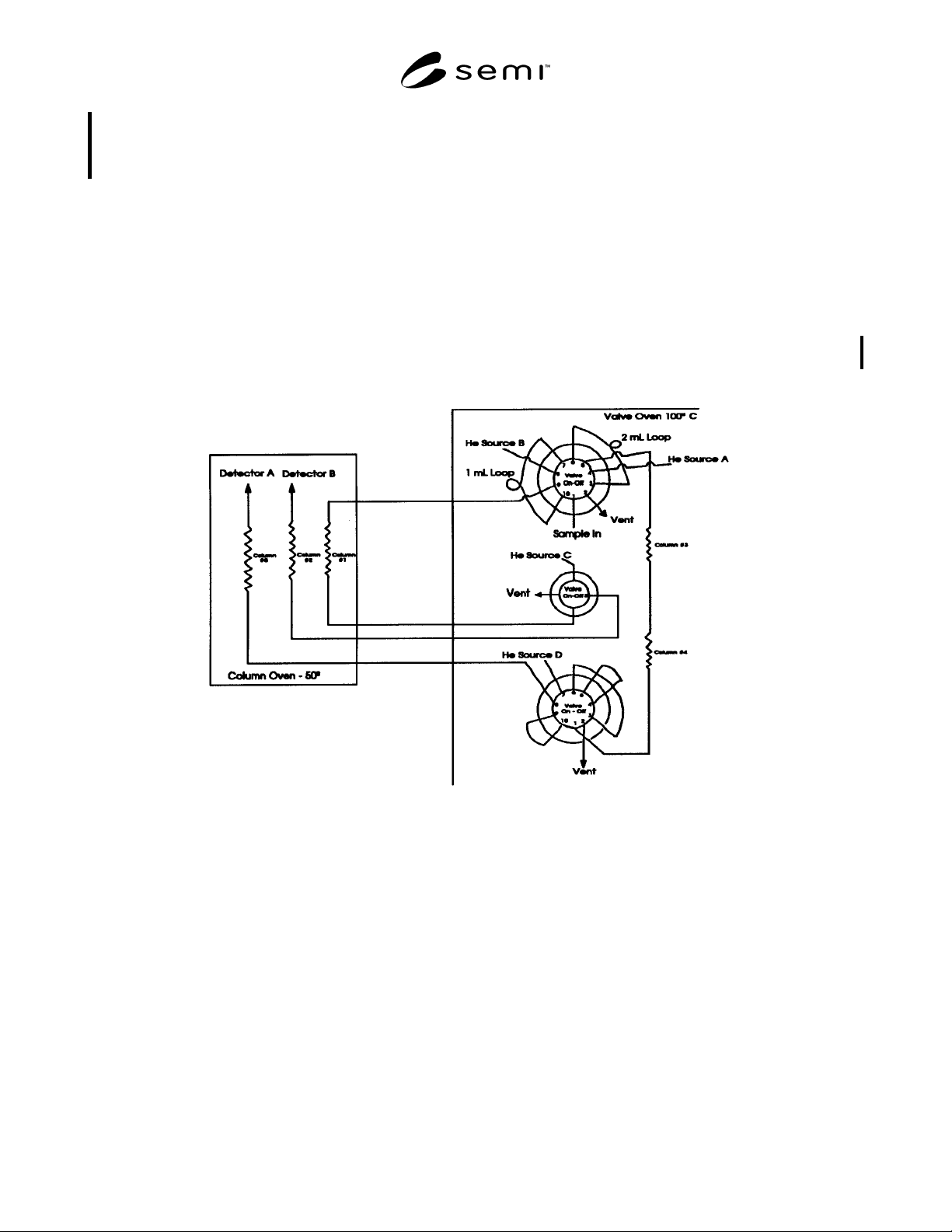
Figure 1
Configuration for the Analysis of CO
2
, O
2
, N
2
, and CO in CF
4