semi合集-English.pdf - 第5761页
SEMI P19-92 © SEM I 1992, 1996 12 Figure 11 Lineari ty Cell Figure 12 Electrical Cell, 2 × n Configura tion NOTICE: T hese st andards do not pu rport to address safety issues, if any, associated with their use. It is the…
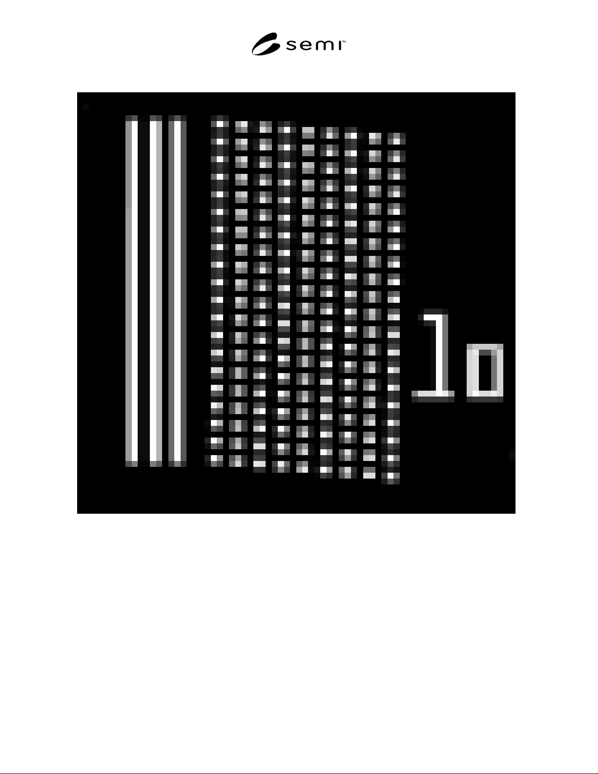
SEMI P19-92 © SEMI 1992, 199611
Figure 10
Staggered Contact Array
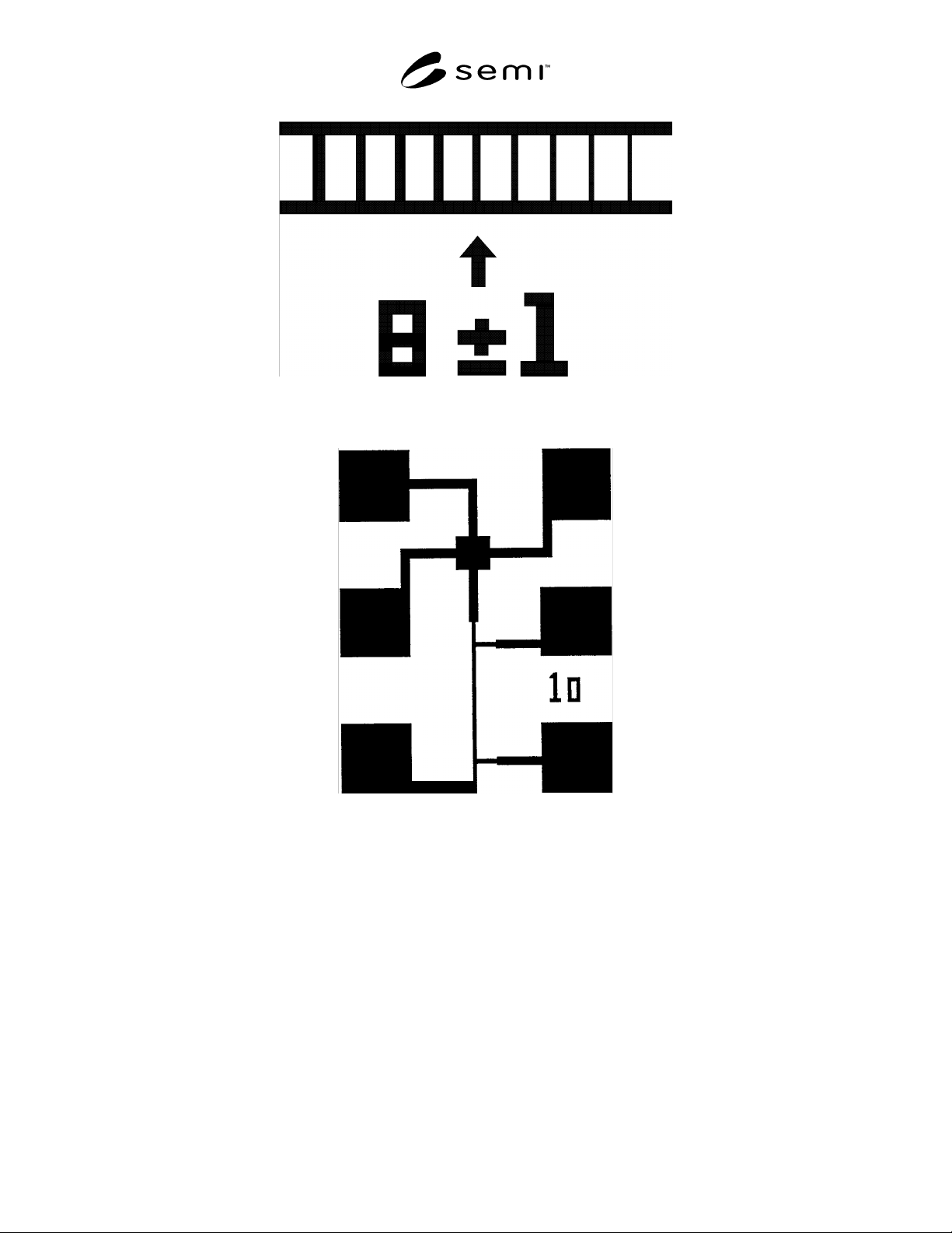
SEMI P19-92 © SEMI 1992, 1996 12
Figure 11
Linearity Cell
Figure 12
Electrical Cell, 2 × n Configuration
NOTICE: These standards do not purport to address safety issues, if any, associated with their use. It is the
responsibility of the user of these standards to establish appropriate safety and health practices and determine the
applicability of regulatory limitations prior to use. SEMI makes no warranties or representations as to the suitability
of the standards set forth herein for any particular application. The determination of the suitability of the standard is
solely the responsibility of the user. Users are cautioned to refer to manufacturer’s instructions, product labels,
product data sheets, and other relevant literature respecting any materials mentioned herein. These standards are
subject to change without notice.
The user’s attention is called to the possibility that compliance with this standard may require use of copyrighted
material or of an invention covered by patent rights. By publication of this standard, SEMI takes no position
respecting the validity of any patent rights or copyrights asserted in connection with any item mentioned in this
standard. Users of this standard are expressly advised that determination of any such patent rights or copyrights, and
the risk of infringement of such rights, are entirely their own responsibility.
Copyright by SEMI® (Semiconductor Equipment and Materials
International), 3081 Zanker Road, San Jose, CA 95134. Reproduction
of the contents in whole or in part is forbidden without express written
consent of SEMI.

SEMI P20-0703 © SEMI 1992, 2003 1
SEMI P20-0703
GUIDELINE FOR CATALOG PUBLICATION OF EB RESIST
PARAMETERS (PROPOSAL)
This guideline was technically approved by the Global Micropatterning Committee and is the direct
responsibility of the Japanese Micropatterning Committee. Current edition approved by the Japanese
Regional Standards Committee on April 28, 2003. Initially available at www.semi.org June 2003; to be
published July 2003. Originally published in 1992.
1 Purpose
1.1 The purpose of this guideline is to provide a
baseline for publications of EB resist parameters. It can
also be used as a guide to evaluate resist process
parameters. This guideline is intended to be applicable
for electron beam processes.
1.2 The parameters for EB Resist publication are
discussed below.
2 Scope
NOTICE: This standard does not purport to address
safety issues, if any, associated with its use. It is the
responsibility of the users of this standard to establish
appropriate safety and health practices and determine
the applicability of regulatory or other limitations prior
to use.
3 Resist Commercial Name
3.1 Describe resist commercial name.
4 Resist Properties
4.1 Polymer Properties
4.1.1 Components — Describe resist components.
Chemical structure is not necessarily required.
4.1.2 Molecular Weight — Describe M
w
, Mn and
M
w
/Mn if known.
4.1.3 Thermal Characteristics — Describe Tg and Tm.
4.2 Resist Solution Properties
4.2.1 Solvent — Specify chemical names.
4.2.2 Viscosity — Solution viscosity, mPa·s, 25°C.
4.2.3 Solid Content — Weight %.
5 Film Forming Properties
5.1 Thickness Curves — Plot film thickness T (µm or
nm) after prebake versus spinning speed R (rpm). Here,
x axis is log (R) and y axis is log (T).
5.2 Conditions — Specify following conditions.
5.2.1 Substrate — Silicon wafer or chrome mask
blank. Specify its structure.
5.2.2 Spinning Conditions — Specify spinning
conditions including coating sequence.
5.2.3 Environmental Conditions — Temperature (°C),
relative humidity (%).
5.2.4 Prebake Conditions — Prebaking temperature
(°C), time (sec), heating and cooling method and
apparatus. Specify heating rate and cooling rate if
monitored.
5.2.5 Thickness Measurement Methods — Thickness
measurement instruments and measurement method. In
case of a light interferance thickness measurement
apparatus, specify the refractive index as a parameter
used in the measurement.
6 Film Thicknesses
6.1 Defines resist thicknesses and measurement
conditions for resist parameter descriptions in and after
Section 10. Unit is µm or nm.
6.1.1 Film Thickness Definitions
6.1.1.1 Ti — Initial thickness after prebake prior to
exposure.
6.1.1.2 Te — Exposed region thickness after
development.
6.1.1.3 Tu — Unexposed region thickness after
development, and after postbake if required.
6.1.1.4 NTe — Te/Ti. Normalized exposed region
thickness.
6.1.1.5 NTu — Tu/Ti. Normalized unexposed region
thickness.
6.1.2 Thickness Measurement Conditions — Thickness
measurement conditions should be the same as
described in Section 5.2.5. In case of measurements of
exposed region thickness, exposed region area should
be larger than 20 µm on all sides.
7 Sample Preparation
7.1 Defines sample preparation methods for resist
parameter descriptions in and after Section 10.
7.1.1 Film Thickness — Ti. 0.50 ± 0.02 µm (500 ± 20
nm) is recommended for a standard thickness.