semi合集-English.pdf - 第4067页
SEMI F55-0600 © SEMI 2000 5 replaced w ith a spool piece. The system can then be continu ously purged with dry N 2 . NOTE 9: The DUT will be c ontam inated with corrosive material. S ee Prec autions in Secti on 10. Prese…

SEMI F55-0600 © SEMI 2000 4
NOTE 6: Data throughout this test may be recorded in a
format similar to that found in Table A1.1.
13.6 Open valve V1 and flow dry N
2
at a setpoint of
80% ± 5% of the DUT FS and wait 10 minutes.
13.7 Record:
13.7.1 DUT setpoint
13.7.2 DUT indicated flow
13.7.3 DUT valve drive output (if available)
13.7.4 Actual flow
13.8 Stop flow by closing V1. Drive the MFC control
valve to a closed position by providing a zero setpoint
or as otherwise provided by the manufacturer. Allow
the MFC indicated flow output to stabilize for a
minimum of three minutes.
13.9 Record the DUT indicated flow and the actual
flow during the zero flow condition.
13.10 Repeat Sections 13.6 through 13.9 twelve times.
This will yield 12 data points for each of the six
measured parameters.
13.11 For each of the six parameters recorded,
perform the following calculation on the 12 baseline
data points to determine the repeatability of the
measurement:
(highest value - lowest value) × 100
average of the 12 values
13.12 If each of the six parameters is not repeatable
within 0.2% during these two hours, subsequent test
data may not be valid and the problem should be
resolved before proceeding with the test.
13.13 Baseline
NOTE 7: Use the averaged value of the measurements made
in Section 13.13 for each parameter as the baseline for that
parameter in the following tests.
13.14 Test Sequence — Without changing the DUT
setpoint, repeat the test sequence in Sections 13.19-
13.22 every 30 minutes, continuously, 24 hours per day,
seven days per week until one of the following test
termination conditions is met.
13.15 The test should not be interrupted because the
DUT may continue to corrode during the interruption,
making test results non-repeatable. The output of the
moisture generator should be measured periodically
during the test sequence to ensure that it remains within
the test specifications.
13.16 Terminate the test sequence if:
13.16.1 The DUT fails to function
13.16.2 The actual-flow shift from baseline exceeds
25%
13.16.3 The valve drive exceeds the manufacturer's
limits
13.16.4 The DUT indicated flow differs from
commanded setpoint by > 5%
13.16.5 The test exceeds 5000 cycles
13.17 Flow dry N
2
for five minutes. After five
minutes, record data on the six test parameters as done
in Section 13.7, interrupting flow to record the DUT
indicated flow and reference flowmeter output at zero
flow. After taking measurements, flow dry N
2
again so
that the total length of this step is 10 minutes. Record
data as shown in Figure 3.
13.18 Flow dry HCl for seven minutes.
13.19 Repeat Section 13.19 and then proceed to
Section 13.22.
13.20 Flow wet N
2
for three minutes. If no test
termination condition is met as described in Section
13.18, repeat Sections 13.19 - 13.22. If a test
termination condition is met, proceed to Section 13.23.
13.21 After the test has been completed, place the
DUT control valve in the purge or fully open position.
Purge with dry N
2
for one hour or at least 50 volume
changes. Cycle the purge gas for 15 seconds on and 15
seconds off by opening and closing V1 for the duration
of the purge. Follow the manufacturer's procedure for
fully opening the DUT control valve.
NOTE 8: Verify purge flow with the reference flowmeter or
by using other means. Corrosion may have rendered the
control valve inoperable. An alternate approach for purging
any corrosive material from the system may have to be
followed.
13.22 Alternate Approach to Purging.
13.23 If gas cannot be purged through the DUT, cycle-
purge each end of the DUT separately using Sections
13.26 through 13.28.
13.24 With valves V2 and V3 closed for the duration
of the procedure, close valve V6 and pressurize both
sides of the system by opening V1 and V7 for 15
seconds.
13.25 Vent pressure through the exhaust system by
closing V1 and opening V6 for 15 seconds.
13.26 Repeat pressure and vent cycles for a minimum
of one hour.
13.27 Remove the DUT. Preserve the test system, if
desired, by taking steps to exclude atmospheric
moisture. Such steps could include capping the system
and shutting all valves. Alternately, the DUT may be
SEMI F55-0600 © SEMI 20005
replaced with a spool piece. The system can then be
continuously purged with dry N
2
.
NOTE 9: The DUT will be contaminated with corrosive
material. See Precautions in Section 10. Preserve the DUT
for failure analysis, if desired.
14 Calculations or Interpretation of Results
14.1 Report data in a tabular format and graph per
Appendix 1. Any parameter which changes more than
1% from its baseline should also be graphed. Note the
reason the test was terminated. Test results may be
summarized in a single parameter by reporting the
number of test cycles to reach a 2% shift in actual flow
or to reach DUT failure, whichever occurs first. In this
test, more data is reported than is required to calculate
the gross test result. The extra data is used when
analyzing test results to determine the cause of failure.
Further explanation of the significance of the data is
beyond the scope of this test method.
15 Data Analysis.
15.1 Calculate any parameter-shift in percent as
follows:
(baseline value - current value) × 100
baseline value
16 Reporting Results
16.1 Report the number of test cycles to reach a 2%
shift in actual flow or to reach DUT failure, whichever
occurs first.
17 Precision and Accuracy
17.1 This method is limited in its precision by the
calibration of the measurement devices, the temperature
of the apparatus, and the concentration of water vapor
in N
2
. Sources of bias are unknown at this time, but
they probably include peculiarities in the construction
of the apparatus.
18 Related Documents
18.1 Material safety data sheet (MSDS) for hydrogen
chloride, which can be obtained from a supplier of the
gas.
19 Illustrations
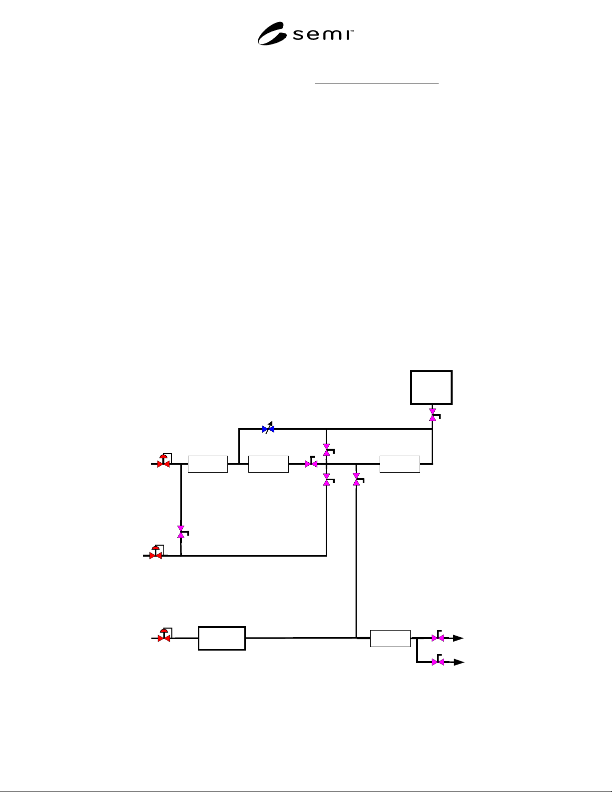
Purge Rate
Flow Meter
MFM
Reference
Meter
DUT
Exhaust
System
Moisture
Generator
MFC
or Control
Valve
Vent
Moisture Level
Test Port
V8
V3
V2
V7
V1
V6
V4
V5
Purge Flow
Dry HCl in
Dry N
2
in
Dry N
2
in
Figure 1
Schematic of Apparatus
SEMI F55-0600 © SEMI 2000 6
Start
Install DUT
Exit
Condition
Basline Data
1 Hour
Flow Dry N
2
Collect Data
10 Minutes
Flow Dry HCl
7 Minutes
Flow Dry N
2
Collect Data
10 Minutes
Flow Wet N
2
3 Minutes
Purge DUT
Remove DUT
Exit
Yes
No
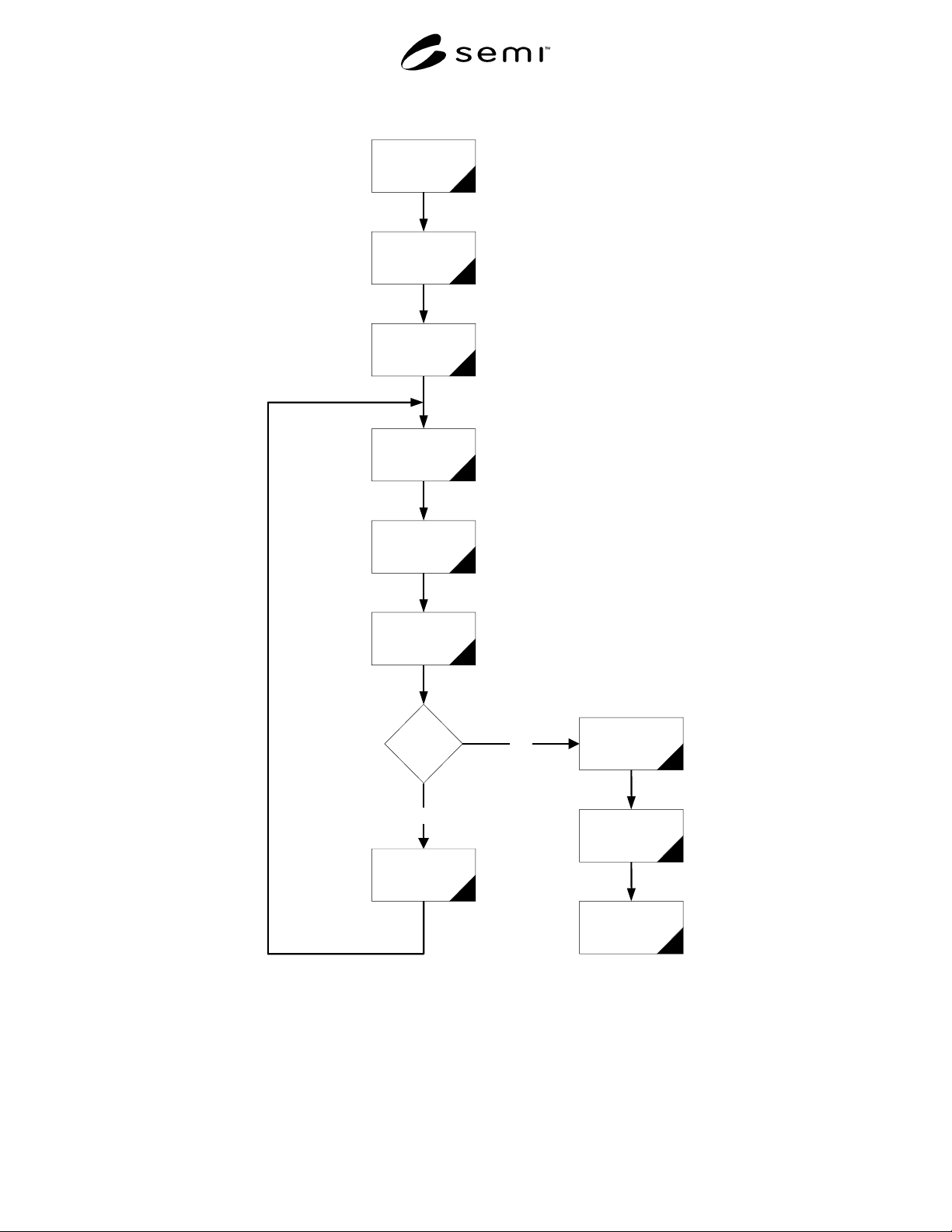
Figure 2
Test Flowchart