semi合集-English.pdf - 第447页
SEMI E64-0600 © SEMI 1997, 2005 2 5.1.6 load port — the interface location on a tool where carriers are placed to allow the tool to process wafers (per SEMI E15). 5.1.7 manual docking — contact m o tion contr olled by th…

SEMI E64-0600 © SEMI 1997, 2005 1
SEMI E64-0600 (Reapproved 0305)
SPECIFICATION FOR 300 mm CART TO SEMI E15.1 DOCKING
INTERFACE PORT
This specification was technically reapproved by the Global Physical Interfaces & Carriers Committee and is
the direct responsibility of the North American Physical Interfaces & Carriers Committee. Current edition
approved by the North American Regional Standards Committee on December 10, 2004. Initially available
at www.semi.org February 2005; to be published March 2005. Originally published in 1997; previously
published June 2000.
1 Purpose
1.1 This specification defines a standard location on SEMI E15.1-compliant tools and requirements to be used for
installing a docking interface for carrier transport carts. It is intended to promote a consistent interface location
between carrier transport carts and SEMI E15.1-compliant wafer process or inspection equipment.
2 Scope
2.1 This standard covers 300 mm SEMI E15.1-compliant tools only. Similar requirements for other tools are not
defined here.
2.2 This standard does not purport to address safety issues, if any, associated with its use. It is the responsibility of
the users of this standard to establish appropriate safety and health practices and determine the applicability of
regulatory limitations prior to use.
NOTICE: This standard does not purport to address safety issues, if any, associated with its use. It is the
responsibility of the users of this standard to establish appropriate safety and health practices and determine the
applicability of regulatory or other limitations prior to use.
3 Limitations
3.1 This standard does not define interface functionality, lead-in, accuracy, carrier transfer, compliance, impact, or
vibration restrictions. Cart and docking interface designs should comprehend physical limitations of tools to which
they are being applied.
4 Referenced Standards
4.1 SEMI Standards
SEMI E15 — Specification for Tool Load Port
SEMI E15.1 — Specification for 300 mm Tool Load Port
SEMI E23 — Specification for Cassette Transfer Parallel I/O Interface
NOTICE: Unless otherwise indicated, all documents cited shall be the latest published versions.
5 Terminology
5.1 Definitions
5.1.1 automatic docking — contact motion is controlled or limited by the design of the cart or interface.
5.1.2 carrier — any cassette, box, pod, or boat that contains wafers (per SEMI E15).
5.1.3 cart — a floor-based carrier transfer vehicle.
5.1.4 docking — the act of locating a floor-based carrier transport vehicle for carrier transfer to/from equipment.
5.1.5 load face plane — the furthest physical vertical boundary plane from carrier centroid on the side(s) of the
equipment where loading of the tool is intended (per SEMI E15).
SEMI E64-0600 © SEMI 1997, 2005 2
5.1.6 load port — the interface location on a tool where carriers are placed to allow the tool to process wafers (per
SEMI E15).
5.1.7 manual docking — contact motion controlled by the operator of the cart.
5.1.8 transfer — to either load or unload (per SEMI E15).
6 Requirements
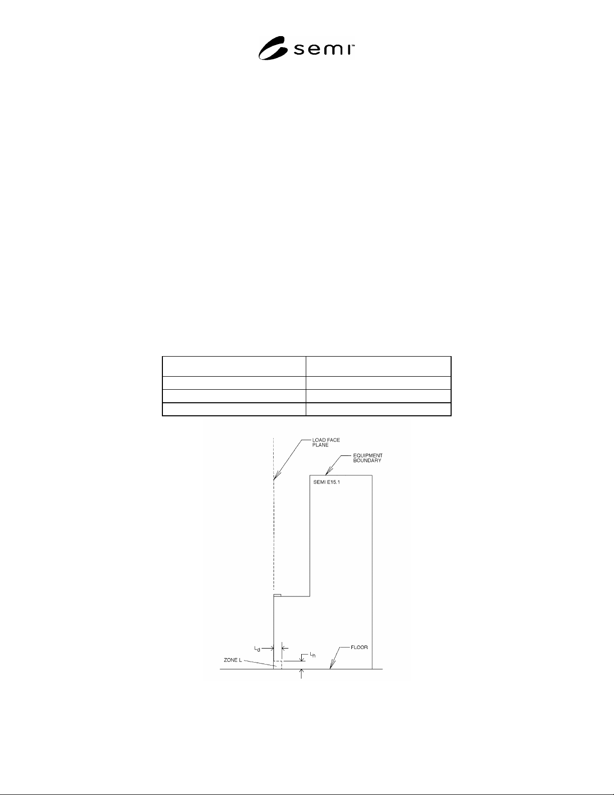
6.1 The following exclusion volume is reserved on SEMI E15.1-compliant tools for the installation of a docking
interface device. This volume is referred to as Zone L.
6.1.1 Interface Zone L — A volume, just above floor level, reserved in SEMI E15.1 for installation of a contact
docking device.
6.1.1.1 The vertical bounds of Zone L are defined by the floor from which Dimension H is measured in SEMI
E15.1 and the Height L
h
, per Table 1.
6.1.1.2 The depth of Zone L into the tool is L
d
, measured from the load face plane as defined in SEMI E15.1.
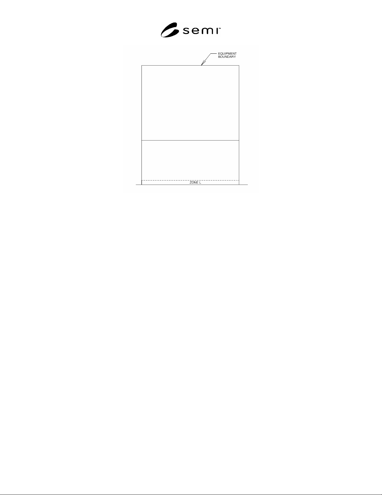
6.1.1.3 The width of Zone L, L
w
, is the full width of the tool measured at the load face plane.
6.1.1.4 A device mounted in Zone L is to be physically isolated from the tool and should be mounted such that the
tool and tool load port are protected from the impact incurred during docking.
6.1.1.5 Since docking devices must be mounted on the floor in Zone L, the equipment must not require the use of
support pedestals or other support structures under the floor below Zone L.
Table 1 Dimensional Requirements for Docking Zone L
Dimension Value, mm (in.)
Zone L depth, L
d
100 (3.9)
Zone L width, L
w
Width of tool
Zone L height, L
h
100 (3.9)
Figure 1
Side Elevation View
SEMI E64-0600 © SEMI 1997, 2005 3
Figure 2
Front Elevation View