semi合集-English.pdf - 第851页
SEMI E114-0302 E © SEMI 2002 5 13.4 At the sho rt circuit termination, the measurement shall be made up to the po int where the falling edge of the impedance i s equal to 90 percent of the nominal impedance. F o r exampl…

SEMI E114-0302
E
© SEMI 2002 4
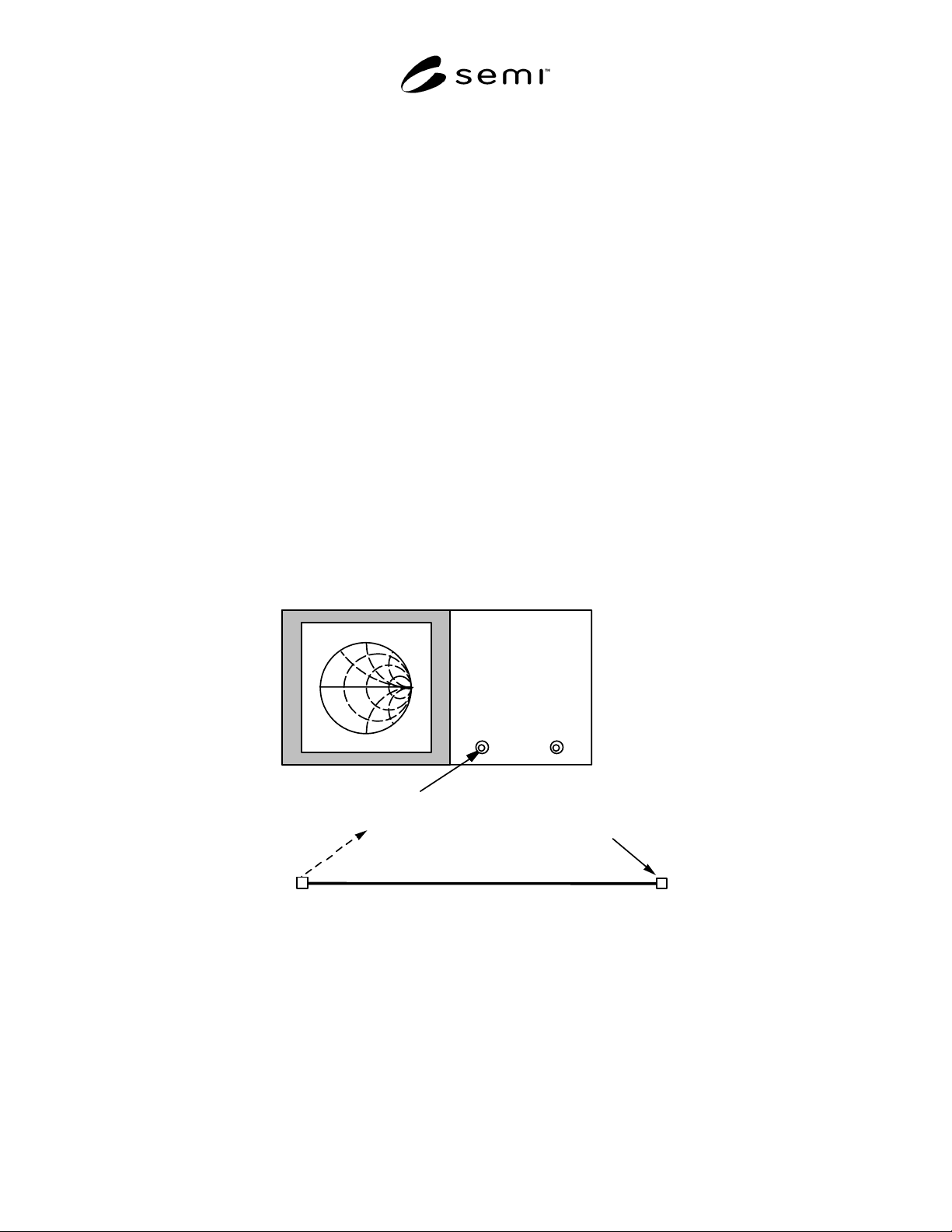
9.4.4 After calibration, the cable assembly to be tested
(DUT) shall be attached to Port 1 on the Network
Analyzer. The other end of the DUT shall be
terminated with a short circuit. After all connections
have been visually inspected to ensure proper contact
and the Network Analyzer measurement has stabilized,
the value of the reflection coefficient phase angle can
be examined.
9.4.5 The indicated frequency where the reflection
coefficient phase angle is ± 180 degrees shall be
recorded. The electrical length of the DUT at the
desired nominal operating frequency (for example,
13.56 MHz) is equal to 180 degrees multiplied by the
ratio of the nominal operating frequency divided by the
measured frequency where the phase angle of the DUT
is equal to ± 180 degrees. For example, if the measured
frequency where the reflection coefficient is ± 180
degrees is 6.1 MHz, then the electrical length of the
DUT at 13.56 MHz is 400.13 degrees (180 × 13.56 /
6.1).
10 Test Setup for Power Dissipation (Loss)
Test
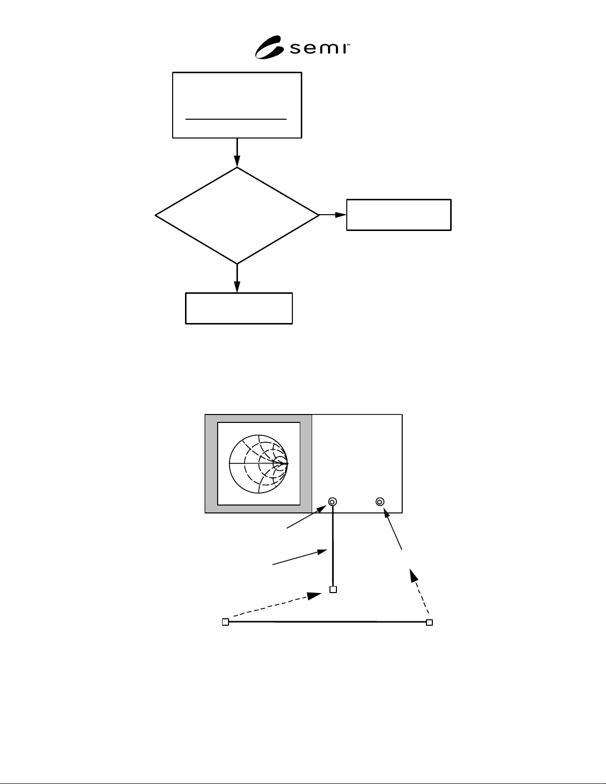
10.1 The Test Setup for the power dissipation (loss)
test consists of the Network Analyzer, the cable
assembly to be tested (DUT), an additional short test
cable (for transmission calibration), the appropriate
adapter (if any) to connect the DUT input to the
network analyzer, and the appropriate adapter (if any)
to connect the DUT output to the network analyzer. A
schematic of the Test Setup is shown in Figure 3.
11 Test Procedure for Determining Power
Dissipation
11.1 The test procedure for determining power
dissipation in cable assemblies will also use a Network
Analyzer. In this case, both Ports of the Network
Analyzer will be used. The transmission coefficient
will be measured (also called the S21 S-parameter).
11.2 Calibrate the Network Analyzer at the desired
operating frequency (for example, 13.56 MHz). If
adapters are to be used to connect the DUT to the
Network Analyzer and/or to the short circuit
termination, then the calibration shall be made with the
adapters in place, along with the additional section of
test cable needed for the calibration. The Network
Analyzer shall be calibrated for measuring the
transmission coefficient, S21 (see Figure 3). The
calibration shall be performed at fixed frequency
(continuous-wave operation) using the lowest
bandwidth possible (typically 10 Hz).
11.3 Connect the cable assembly DUT between the two
test Ports on the Network Analyzer (including the
additional test cable used for calibration). After
visually inspecting the connections to ensure proper
contact and the Network Analyzer measurement has
stabilized, the value of the transmission coefficient
(S21) shall be recorded.
11.4 The recorded number shall be expressed in terms
of dB (decibels) and percentage of power transferred in
the DUT. The conversion between dB and percentage
is expressed as:
)10/dBin loss(
10100% ×=TransferPower
For example, if the transmission coefficient is measured
to be –0.4 dB, then the power transfer percentage would
be 91.2%. In other words, 8.8% of the power is lost in
the DUT.
12 Test Setup for Characteristic Impedance
Variation Measurement
12.1 The Test Setup for the Characteristic Impedance
variation measurement consists of a Time Domain
Reflectometer (TDR), the cable assembly to be tested
(DUT), the appropriate adapter (if any) to connect the
DUT input to the TDR, and a standard 50-ohm load
termination (see Figure 4).
12.2 Prior to making any measurements, the TDR shall
be turned on and allowed to warm up. This time allows
for electronics to come to a stable operating condition
for the measurements.
13 Test Procedure for Determining
Characteristic Impedance
13.1 Connect a standard 50-ohm load termination to
the input of the TDR and measure the impedance. This
measurement determines the normalization factor for
the measured impedances. All reported measurements
shall be scaled by this factor by multiplying subsequent
measurements by the ratio of 50 divided by the
impedance value measured with the 50-ohm standard
load.
13.2 Prior to measuring the DUT, the nominal velocity
of propagation of the cable shall be entered into the
TDR. For example, the velocity of propagation is 0.66
for cable type RG-217.
13.3 Connect one end of the DUT to the TDR and
terminate the other end of the DUT with a short circuit.
Measure the characteristic impedance as a function of
distance along the DUT by moving the measurement
distance indicator of the TDR. Record the minimum
and maximum impedance measured over the length of
the cable assembly. The measurement shall be made
throughout the length of the DUT, including the
connectors, up to the short circuit termination.
SEMI E114-0302
E
© SEMI 2002 5
13.4 At the short circuit termination, the measurement
shall be made up to the point where the falling edge of
the impedance is equal to 90 percent of the nominal
impedance. For example, if the nominal impedance is
50 ohms, then the measurement can stop at the point
where the measured value at the short circuit
termination is equal to 45 ohms (0.9 × 50 = 45). An
example plot showing the measurement termination
point is shown in Figure 5.
NOTE 1: The termination point can be verified by
disconnecting the short circuit termination and observing that
the impedance increases rapidly due to the open circuit.
14 Reporting Test Results
14.1 Report the type of Network Analyzer and the
details of the Network Analyzer parameters used for the
tests, including the bandwidth, the number of data
points, the test frequency, and the frequency span (if
any). An example data sheet is shown in Table 1.
14.2 Report the type of Time Domain Reflectometer
used for the test.
14.3 Report the length of the cable assembly in terms
of degrees at the nominal operating frequency.
14.4 Report the power dissipation in terms of dB
(decibels) and percentage of power transfer.
14.5 Report the variation in characteristic impedance in
terms of the minimum and maximum after the values
have been scaled according to the reference 50-ohm
load.
15 Related Documents
15.1 IEEE Standards
1
IEEE-STD-572 — IEEE Standard for Qualification of
Class 1E Connection Assemblies for Nuclear Power
Generating Stations
15.2 MIL-Specifications
2
MIL-PRF-31031A — General Specification for
Connectors, Electrical, Plugs and Receptacles, Coaxial,
Radio Frequency, High Reliability, for Flexible and
Semirigid Cables
MIL-STD-348A — Radio Frequency Connector
Interfaces for MIL-C-3643, MIL-C-3650, MIL-C-3655,
MIL-C-25516, MIL-C-26637, MIL-PRF-39012, MIL-
PRF-49142, MIL-PRF-55339, and MIL C-83517
MIL-STD-220B — Test Method Standard: Method of
Insertion Loss Measurement
Port 1
Short Circuit
Termination
Cable Assembly to be tested
Network
A
nal
y
zer
NOTE: The reflection coefficient calibration is at the Port 1 output. The cable assembly to be tested (DUT) attaches to Port 1
and is terminated with a short circuit.
Figure 1
Schematic of the Network Analyzer Test Setup for the Electrical Length Measurement
SEMI E114-0302
E
© SEMI 2002 6
Estimate the
Free-Space Length
of Cable Assembly
Physical Length
Velocity of Propagation
[]
Is the
Estimated Length
Less Than a Quarter Wavelength
at the Nominal Operating
Frequency?
Use Test Method 1
to Measure Wavelength
Use Test Method 2
to Measure Wavelength
Yes
No
Figure 2
Flow Chart Showing the Steps to Chose the Appropriate Test Method for Determining Electrical Length of
the Cable Assembly
Port 1
Port 2
A
dditional Test Cable
Cable Assembly to be tested
Network
A
nal
y
zer
NOTE: Both the Port 1 and Port 2 outputs need to be used for the measurement. An additional test cable is needed for the
transmission calibration between the two ports. The cable assembly to be tested (DUT) attaches between the additional test cable
on Port 1 and Port 2.
Figure 3
Schematic of the Network Analyzer Test Setup for the Power Dissipation (loss) Measurement