semi合集-English.pdf - 第4601页
SEMI D36-1103 © SEMI 2003 1 SEMI D36-1103 TERMINOLOGY FOR LC D BACKLIGHT UNIT This standard was technically a pproved by the Global Flat Panel Di spla y Committee and is the direct responsibility of the Japanese Flat Pan…
SEMI D35-1103
E
© SEMI 2003 12
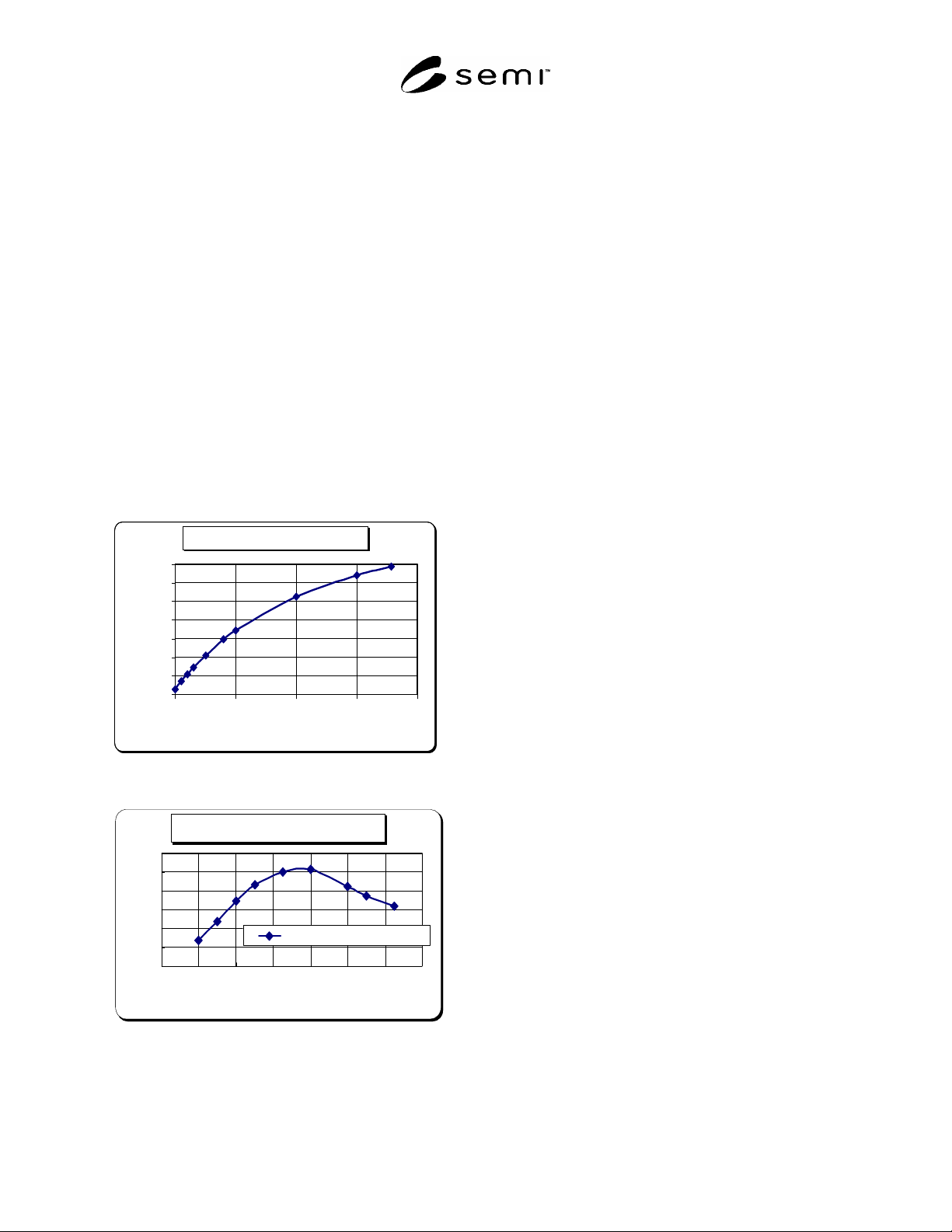
R3-3.4 On the other hand, when the temperature is
high, the mercury molecule density goes up
dramatically, reabsorption of ultraviolet rays by
mercury itself takes place, the amount of ultraviolet
rays that reach the fluorescent substance decreases and
so the luminance decreases accordingly. The further
attention necessary is that the mass (thickness) of glass
tube is made as thin as possible because the CCFL has
been developed with such top priority as to have the
narrow diameter, space-saving shape and high
luminance. For this reason, the heat capacity is very
small, which means the inside mercury molecule
temperature will be affected greatly by heat transfer
caused by interference with surrounding members and
cooling effect of convective wind to the glass.
R3-3.5 Since the luminance varies due to the impact to
the glass temperature by each parameter such as the
interference of surrounding members, contact of other
materials and cooling effect of convective wind, it is
recommended that measuring conditions should be
specified and standardized as much as possible.
Tem p. vs M ercury vapor
0.0001
0.001
0.01
0.1
1
10
100
1000
0 100 200 300 400
Temp. (
℃
)
Vaper pressure
(
mmHg
)
Ambient Tem p. v s L u m inance
0
20
40
60
80
100
120
-40 -20 0 20 40 60 80 100
Ambient Tem p. (℃ )
Lum inance variation
(% )
Luminance(100% at 25
℃
)
Tem p. vs M ercury vapor
0.0001
0.001
0.01
0.1
1
10
100
1000
0 100 200 300 400
Temp. (
℃
)
Vaper pressure
(
mmHg
)
Ambient Tem p. v s L u m inance
0
20
40
60
80
100
120
-40 -20 0 20 40 60 80 100
Ambient Tem p. (℃ )
Lum inance variation
(% )
Luminance(100% at 25
℃
)
R3-4 Slide-up Speed
R3-4.1 The status where a main discharge starts is
measured for the measurement of stable discharge
voltage sliding gradually the voltage up from the
sufficiently low value. Since the starting point of main
discharge may vary by the slide-up speed, a special
attention should be paid.
R3-4.2 When the slide-up speed is so slow that the
ratio of partial pressure of Ar, Ne and Hg shifts to the
condition where lighting is easily performed because
the mercury vapor pressure increases by the heat
generation caused by half-lighting, the main discharge
may begin easily compared to the condition at low
CCFL temperature.
R3-4.3 Therefore, when measuring the CCFL, these
conditions should be specified and standardized as
much as possible.
R3-5 Use of Master CCFL
R3-5.1 When interrelating the spectroradiometer and
colorimeter, an actual CCFL is used often as a master
CCFL.
Precautions for such cases are
1) the registration date, production history, lighting
history and expiring date of the master CCFL
should be specified and attached to it, and
2) the master CCFL should be kept such that there
shall be no impact to reproduction of
measurement.
R3-5.2 Since this document is positioned as a related
document to standardized documents, the contents are
treated as “just for information”.
NOTICE: SEMI makes no warranties or
representations as to the suitability of the standards set
forth herein for any particular application. The
determination of the suitability of the standard is solely
the responsibility of the user. Users are cautioned to
refer to manufacturer's instructions, product labels,
product data sheets, and other relevant literature,
respecting any materials or equipment mentioned
herein. These standards are subject to change without
notice.
By publication of this standard, Semiconductor
Equipment and Materials International (SEMI) takes no
position respecting the validity of any patent rights or
copyrights asserted in connection with any items
mentioned in this standard. Users of this standard are
expressly advised that determination of any such patent
rights or copyrights, and the risk of infringement of
such rights are entirely their own responsibility.
Copyright by SEMI® (Semiconductor Equipment and Materials
International), 3081 Zanker Road, San Jose, CA 95134. Reproduction of
the contents in whole or in part is forbidden without express written
consent of SEMI.
SEMI D36-1103 © SEMI 2003 1
SEMI D36-1103
TERMINOLOGY FOR LCD BACKLIGHT UNIT
This standard was technically approved by the Global Flat Panel Display Committee and is the direct
responsibility of the Japanese Flat Panel Display Committee. Current edition approved by the Japanese
Regional Standards Committee on August 8, 2003. Initially available at www.semi.org October 2003; to be
published July 2003.
1 Purpose
1.1 These terms and definitions describe various
components and characteristics of backlight unit used
for light source of liquid crystal display. This standard
will be helpful to unify terminologies used for backlight
unit, which will improve manufacturing efficiency
resulting in reduction of manufacturing cost and time.
2 Scope
2.1 This standard is applicable to backlight unit. This
standard includes the terminologies of components used
in Backlight unit, inspection and measurement used in
backlight unit field as well as panel and instrumentation
field. The other area is not dealt with other SEMI
standard document.
NOTICE: This standard does not purport to address
safety issues, if any, associated with its use. It is the
responsibility of the users of this standard to establish
appropriate safety and health practices and determine
the applicability of regulatory or other limitations prior
to use.
3 Limitations
3.1 In this standard, our target is only backlight unit
and general purpose for terminology. Hence a special
language used for critical purpose is not mentioned. For
example, we do not define special languages depending
to personal emotion and a detail or small components
depending on special or general purpose.
3.2 The definition of lamp components follows the
language used in lighting company or other optics
related standardization.
4 Referenced Standards
4.1 CIE Standards
1
CIE 1931 — color space, CIE 1976 UCS
NOTICE: Unless otherwise indicated, all documents
cited shall be the latest published versions.
1 CIE International Commission on Illumination, Kegelgasse 27, A-
1030 Vienna, Austria
5 Terminology
5.1 General Terminology
5.1.1 Definition of Backlight Unit
5.1.1.1 Backlight unit (BLU) is a kind of light source
positioned at the backside of liquid crystal panel. Since
LCD is non-emissive display device it needs essentially
light source.
5.1.2 Structure of BLU
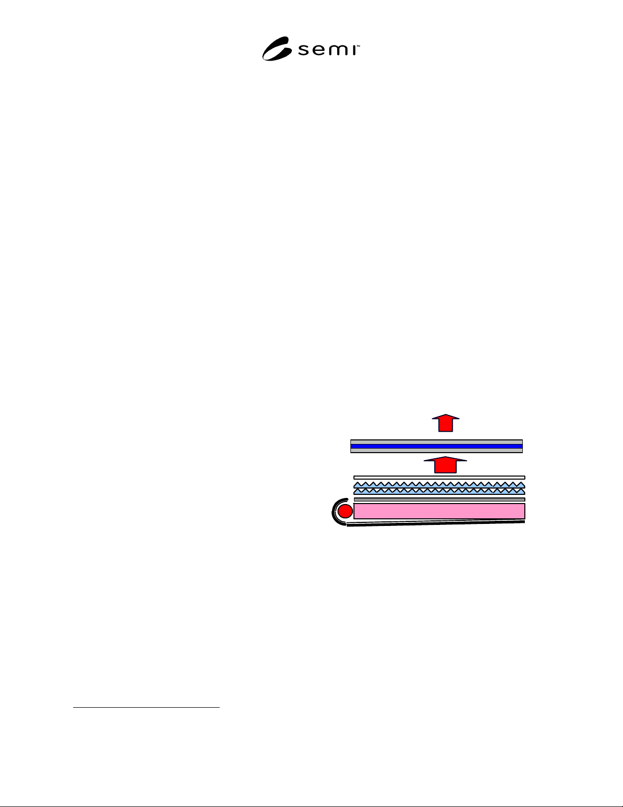
5.1.2.1 As an initial light source cold cathode
fluorescence lamp (CCFL) is used at bottom and/or
topside of BLU. The light emitted from CCFL is
entered into light guide plate (LGP). Here light is
spread out two-dimensional light by scattering sites at
the back surface LGP or inside of LGP. Two-
dimensional light is sometimes diffused by diffusion
sheet or conversed by prism sheet respectively. And
final light comes into human eyes.
g
e
d
c
b
f
a
Figure 1
General structure of BLU; From a) to g), each
components are indicate CCFL, reflection sheet,
light guide plate, diffusion sheet, two prism sheets,
protection sheet and panel respectively.
5.2 Components — The following measurement items
are recommended for BLU but these items depend on
user requirements if they are specified.
5.2.1 cold cathode fluorescence lamp — the positive
column or cathode discharge lamp of the glow
discharge. Namely, the ultraviolet by the releasing of
the second electron of cathode stimulates the phosphor,
so the lamp radiates the visible ray.

SEMI D36-1103 © SEMI 2003 2
5.2.2 reflection sheet — the sheet that reflects the light
to prevent the loss of the light toward back side of the
BLU.
5.2.3 light guide plate — the plate, one of important
components of the BLU, that changes the path of the
light from line light source to face light source.
5.2.4 diffusion sheet — the sheet that diffuses the light
to the previous surface.
5.2.5 prism sheet — the film to enhance the brightness.
5.2.6 protection sheet — a kind of sheet placed on the
top of BLU for protecting other components from
damage outside.
5.2.7 frame — the frame to make the components of
the BLU stably combined.
5.2.8 electrode — the conductor, an electron source
inside the lamp, which releases the electron by the
electric current or flows the discharge current.
5.2.9 hot (electrode) — the electrode part receiving
current from the inverter, namely anode.
5.2.10 ground (electrode) — the opposite part against
the hot electrode of the lamp, namely cathode.
5.2.11 inverter — the device that transfers the voltage
of the power supply from low voltage DC to high
voltage AC to start the cold cathode fluorescence lamp.
5.2.12 lamp — the light source device mainly using the
cold cathode fluorescence lamp that lights the BLU.
5.2.13 lamp assembly — the total light source devices
to light lamp.
5.2.14 lamp cover — the part protecting the lamp
makes the light released from the luminance factor
incident over the light guide plate.
5.2.15 lamp holder — the part that protects the lamp
form external collision or contact.
5.2.16 lamp ring — the part that protects lamp from the
fragility.
5.2.17 mercury — as an ultraviolet light source,
elemental name in the periodic table is Hg.
5.2.18 mixing gas — the gas needed to open the
discharge consists of Neon and Argon gas etc
maintaining the discharge.
5.2.19 phosphor — the phosphor with commonly red,
blue and green color that transfers the ultraviolet came
from the mercury to the visible ray.
5.2.20 shrinkage tube — the part made of insulation
material to protect the wire.
5.2.21 adhesive tape — the tape to be used for adhering
the components of the BLU to each other.
5.2.22 back cover — the device that complements
fragile part of the lamp, etc. by means of utensil.
5.2.23 clip — the part fixing the sheet on the frame to
prevent flux and looseness of sheet.
5.3 Characteristics
5.3.1 luminance — the luminance flux from the surface
per unit solid angle per unit area in a given direction.
Unit: nit and/or cd/m
2
5.3.2 average luminance — average value of measured
luminance.
5.3.3 maximum luminance — maximum value among
the measured luminance.
5.3.4 minimum luminance – minimum value among the
measured luminance.
5.3.5 luminance uniformity — The value that indicates
the uniformity of luminance for the measured point.
And the value is obtained by selecting one or multiple
among below equations.
a) (maximum/minimum) × 100
b) (minimum/maximum) × 100
c) [(maximum-minimum)/Maximum] × 100
d) [(maximum-minimum)/Average] × 100
where average = Σ(i!n)/N
5.3.6 center point — The position corresponding to the
center of active area of BLU.
5.3.7 chromaticity — The indication of the suitable
color for the mark of same color, namely the spectro-
distribution-chart (λ) of the measured light source. The
light source color is indicated by the 3 measured
stimulus factors X, Y, Z (the quality of stimulus
evoking the primary color sense) at the sensitivity of
eye (2° ).
Tri
stimulus factors: X, Y, Z
x = X/(X + Y + Z),
y = Y/(X + Y + Z),
z = Z/(X + Y + Z),
x + y + z = 1
(Referred by CIE 1931 color space)
5.3.8 life time — The shorter period of the time during
no re-lit the lamp when lighting the lamp and during the
flux of light’s reaching the minimum value of
regulations.