semi合集-English.pdf - 第889页
SEMI E116-0705 © SEMI 2002, 2005 21 R1-4.2 The advantages of appl ying Equi pment Performa nce Tracking to the Carrier Handling Module a re as follows: Any equipment, except certain specific ones such as an expose tool…
SEMI E116-0705 © SEMI 2002, 2005 20
Tool Type Modules
Metrology Loadports Central
Wafer
Handler
Align-ment
Stage
Measure-
ment Stage
Inspection Loadports Inspection
Stage
Handler
Probe / Test Loadports Probe/ Test
Platform
Handler
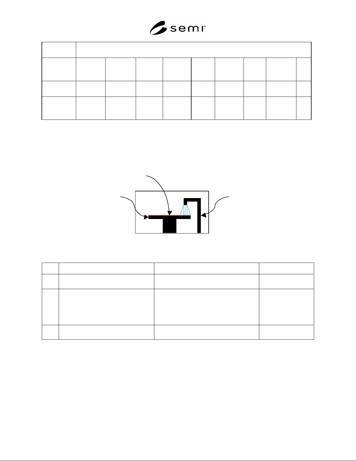
R1-2 EPT Module / Task Definition Example
R1-2.1 Figure R1-1 shows a simple module and the associated actions/tasks that correspond. The EPT Tasks have
been diluted to the level that will allow a serial chain of tasks to occur. The Internal Tasks column is present to
show that the equipment may have much more happening concurrently at a more detailed level. Table R1-2 shows a
possible task-based process flow in this module.
Spinning substrate Dispensing resist
Substrate load/unload
Figure R1-1
Example EPT Module
Table R1-2 Example EPT Tasks
Step Action Possible Internal Tasks EPT Active Task
1 Loading the substrate Receiving the substrate
Substrate alignment
Substrate load
2 Coating the substrate Substrate spin (accelerate)
Substrate spin (steady)
Dispense resist
Substrate spin (decelerate)
Substrate coat
3 Unloading the substrate Substrate alignment
Substrate removal
Substrate unload
R1-3 An Example of Equipment Performance Tracking on a Carrier Handling Module
R1-3.1 This section provides examples of equipment performance tracking to clarify the application of the standard
to modules that are part of the Equipment Front-End Module (EFEM).
R1-4 Carrier Handling Module (CHM)
R1-4.1 The Carrier Handler is a part of EFEM, excluding any Substrate Handler, which is defined in SEMI E101. A
Carrier Handling Module is similar but different from the definition. It is a more general subsystem to handle
carriers without handling substrates in EFEM that is applicable to various analyses and applications. The Carrier
Handling Module is a logical module that may or may not represent an existing physical module.

SEMI E116-0705 © SEMI 2002, 2005 21
R1-4.2 The advantages of applying Equipment Performance Tracking to the Carrier Handling Module are as
follows:
Any equipment, except certain specific ones such as an expose tool within a linked litho tool in the lithography
process, has one or more Carrier Handling Modules.
The state of the Carrier Handling Module leads to whole input and output of material to and from an equipment.
Monitoring the Equipment Performance Tracking state of the Carrier Handling Module helps control loading to
or unloading from equipment on appropriate time.
The state can reveal what related SEMI standards, i.e. SEMI E87 and SEMI E90, may not address.
Estimation of capabilities about sub-components on a Carrier Handling Module is available with tracking the
state.
Each component that makes up the Carrier Handling Module may experience mechanical failure. This can cause
the entire Carrier Handling Module to be in an out of service state. Tracking time between failures would be
valuable.
R1-5 Components to track performance of Carrier Handling Module
R1-5.1 Generally, a Carrier Handling Module has the following components.
Carrier Handoff PIO (SEMI E84) Port
Carrier Transfer Mechanism
Carrier ID Reader
Carrier ID Writer
FOUP Opener
Carrier Slot Mapper
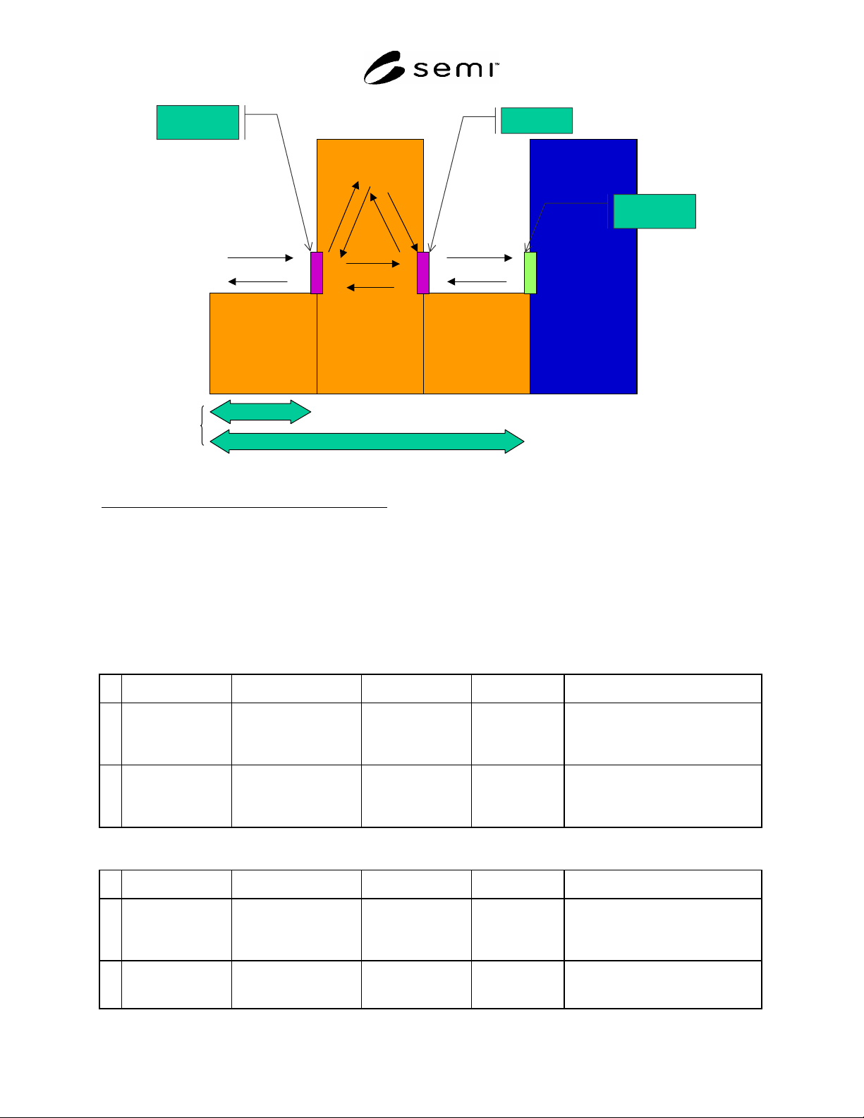
R1-5.2 This section investigates the following composition to represent examples for Fixed Buffer type and Internal
Buffer type equipment. An example of a Carrier Handling Module is illustrated in Figure R1-2. Number of installed
components are listed in the Table R1-3.
Table R1-3 Typical Composition of Carrier Handoff Module
Number Installed Carrier Handoff
PIO
Carrier Transfer
Mechanism
Carrier ID
Reader
Carrier ID
Writer
FOUP
Opener
Slot Mapper
Internal Buffer Type 2 4 2 1 1 1
Fixed Buffer Type 2 2 2 2 2 2
#1
Several Carrier Transfer Mechanisms are usually docking mechanism for Fixed Buffer type. For Internal Buffer type, one of them is a Carrier
Transfer Robot in internal buffer, one is a Docking Mechanism inside the internal buffer and the other one is Carrier Transfer Mechanism to pass
carrier between Load Port and the Internal Buffer.
SEMI E116-0705 © SEMI 2002, 2005 22
FB Type
TA TB TC
Equipment
(Process Area)
exit
entrance
IB Type
FIMS face
CHM
Figure R1-2
Carrier Handling Module
In Diagram R1-2, the following translation applies
FB Type = Fixed Buffer Type
IB Type = Internal Buffer Type
TA = Transport A
TB = Transport B
TC = Transport C
R1-6 Triggers of Transition for each Components of Carrier Handling Module
The following tables describe triggers to change the state of components for specific tasks.
Table R1-4 Triggers of Transitions for Specific Tasks of Carrier Handoff PIO
# Previous State Trigger New State Action(s) Comment
2 IDLE Receiving VALID
signal in SEMI E84.
BUSY Set off handoff
sequence
Loading or Unloading sequence.
Processing or moving wafers
between carrier and process
container before Unloading.
3 BUSY Receiving COMPT
signal in SEMI E84 or
Timeout in handoff
sequence.
IDLE Waiting
disconnected
Loading or Unloading sequence is
completed or terminated. Processing
or moving wafers between carrier
and process container after Loading.
Table R1-5 Triggers of Transitions for Specific Tasks of Carrier Transfer Mechanism on Loadport of Fixed
Buffer Type or FIMS Port of IB
# Previous State Trigger New State Action(s) Comment
2 IDLE Docking or Undocking
Started
BUSY None Carrier moving sequence before
docking. Processing or moving
wafers between carrier and process
container before undocking.
3 BUSY Docking or Undocking
Complete
IDLE None Processing or moving wafers
between carrier and process
container after docking.