semi合集-English.pdf - 第4550页
SEMI D26-1000 © SEM I 2000 9 7.8.5 D esign Rules — A com prehe n s i ve and we ll- presented set of desi gn rules is an invaluable communication tool bet ween the cus tomer and supplier. For the m anufacture of large are…
SEMI D26-1000 © SEMI 2000 8
• Outlines constructed with ARC and LINE that do
not match exactly at the corners
• Duplicated entities
• Self-intersecting poly-lines
• VERTEX flags options
• TAPERED POLYLINE entities (different start and
end width), straight or arced
• SHAPE entities
• ELLIPSE entities
• "Stretched” BLOCK entities – blocks with
different X- and Y-scale factor
• Rotated BLOCK entities
• POINT entities
• Any of the "Curve-fitted" POLYLINE entities,
such as "SPLINE" shapes
• “Paint & Scratch” LAYER entities without a
specific identification of which layers should be
opaque and which should be clear, and in which
order.
• TEXT entities without the appropriate font files.
• TEXT entities with special attributes (mirror,
rotate, slant, etc.).
• XREF BLOCK entities.
• Non-decimal linear and angular coordinates.
• Radian angular units.
7.8.2.2 Gerber
• Self-intersecting entities (line draws, outlines,
“butterfly targets”, etc.).
• Arrayed arrays (nested).
• Drawn apertures using shapes other than round
(square apertures may be used only if drawn
parallel to either axis).
7.8.3 Recommended Practices — The following is a
summary of some recommended design practices DXF
and Gerber data formats.
7.8.3.1 DXF
• SOLID entities
• TRACE entities
• CIRCLE entities
• BLOCKS, with a minimum level of nesting as
required by the design
• Closed, zero width POLYLINE or LWPOLYLINE
entities to describe complex CAD feature outlines
• TEXT objects that are exploded and exported as
POLYLINE entities, either as closed zero width, or
POLYLINE entities with width
• Decimal units for inches, mils, millimeters,
microns, or degrees.
7.8.4 Gerber
• Subfigure or SR codes.
• POEX/POIN or G36/G37 codes.
• Complex apertures and aperture macros.
• Embedded apertures and parameters.
40 um
40 um
1500 um
800 um
10 mm
10 mm
Target
Photomask
4X Targets
200um borde
r
around this
target
Figure 6
Location and Pattern

SEMI D26-1000 © SEMI 20009
7.8.5 Design Rules — A comprehensive and well-
presented set of design rules is an invaluable
communication tool between the customer and supplier.
For the manufacture of large area precision glass and
quartz substrate photomasks having geometry’s in the
low to sub-micron range, design rules are an essential
component of any successful program designed to
minimize the risks of introducing errors and delays into
the process.
7.8.5.1 The best match occurs when there is a
commonality between the customer’s design
capabilities and vendor’s requirements.
7.8.5.2 Design rule documents are usually unique to
each Large Area Mask supplier, and the details depend
mainly upon the vendor’s software repertoire and their
ability to process certain types of data.
7.8.5.3 The type of Computer Aided Design software
package used by the customer to design their product
must be capable of either exporting data in a format that
the vendor can readily use, or the vendor must be
capable of using data in the native format of the
customer’s design package.
8 Test Methods
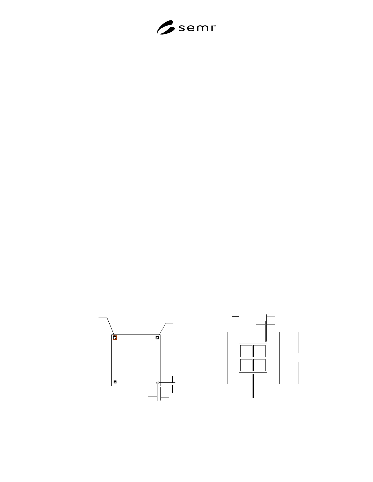
8.1 Auto Inspection Artifacts — To perform any
automated inspection of a photomask, the inspection
equipment and photomask pattern must be precisely
located. This is done with four alignment targets on the
photomask. The alignment targets are part of the
photomask pattern and are located near each corner of
the photomask. The target in the upper left corner will
also have a 200 micron border around it with a 10
micron space between the target and the border. When
appropriate, this additional border will also be used as a
closure test by exposing the targets first and then the
border at the end of the plate exposure.
8.1.1 4 Alignment targets provide optimum alignment
accuracy.
8.1.2 Greater distance between the targets provides
greater alignment accuracy.
8.1.3 The target locations near the edge of the glass
provide the maximum product image area.
8.1.4 The target pattern can be easily located visually
on the photomask.
8.1.5 The target can be clear on dark or dark on clear.
9 Product Labeling
9.1 General — Large Area Masks used in FPD
manufacturing are valuable, fragile and prone to
contamination prior to use. The content of a LAM is
difficult to discern unless each unit contains a unique
ID that can be read by various tools. To simplify
AMHS and process/metrology tool operations, this ID
needs to be consistently readable on the bare mask, with
and without resist coating; ideally it would be readable
through the plastic container in which the mask is
shipped. See Figures 7–10.
9.2 Summary — The labeling specified herein consists
of a rectangular two-dimensional (2-D), machine-
readable, binary Data Matrix symbology located on the
pattern surface of LAMs, within the edge region and
near the orientation corner. The specification defines a
46-character default message that is included in all
mark fields, and option for up to 26 additional
characters, for a total of 72 message characters (see
SEMI T8).
9.3 Field Construction — While this specification
does not specify the marking techniques that may be
employed when complying with its requirements, it is
assumed the symbol may be obtained through
lithographic techniques, for instance during the mask
exposure sequence.
9.4 Shape and Size of the Data Matrix Code Symbol
9.4.1 Data Matrix Code Symbol Dimensions
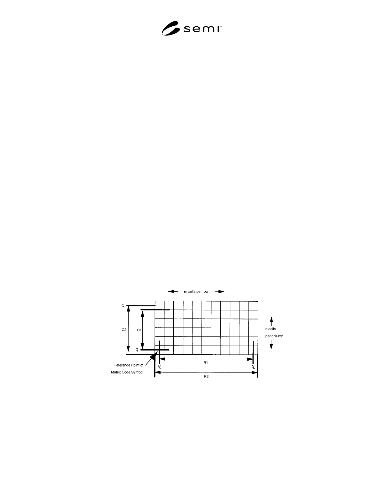
9.4.1.1 Each rectangular matrix code symbol shall be
composed of an array of 16 rows and 36 or 48 columns
as defined in AIM International Symbology
Specification – Data Matrix. It may contain an
alignment bar.
9.4.1.2 Cell spacing shall be 25 µm, center to center.
9.4.1.3 Matrix code symbol nominal dimensions are:
a. 4 × 9 mm, for a 16 row × 36 column field, or
b. 4 × 12 mm, for a 16 row × 48 column field.
9.4.2 Dot Size — The nominal shape of the dot
produced in the matrix may be circular or square. Its
diameter or edge length shall be 250 ± 10 µm.
9.4.3 Border Rows and Columns (see Figure 9)
9.4.3.1 One border row and one border column shall
contain a dot in each cell. There are identified as the
primary border row and the primary border column.
These are used by the code reader to determine the
orientation of the matrix.
9.4.3.2 The opposing (secondary) border row and
column shall contain dots in alternating cells.
9.4.3.3 For these rectangular matrix code symbols, the
reference point of the symbol shall be the physical
center point of the cell common to the primary border
row and the primary border column.
SEMI D26-1000 © SEMI 2000 10
9.5 Content of the Data Matrix Co de Symbol
9.5.1 Each rectangular matrix code symbol shall
contain between 46 message characters (for 16 rows ×
36 columns) and 72 message characters (for 16 rows ×
48 columns), encoded in accordance with AIM
International Symbology Specification – Data Matrix.
9.5.2 The message characters may include any of
those designated as “mostly upper case” Annex K of
AIM International Symbology Specification – Data
Matrix. 8-bit characters may also be encoded with
reduced field capacity. The first 20 characters shall
contain two elements:
a. a vendor-assigned 15-character mask identification
code, followed
by
b. a 1-character field concatenation symbol (+) and 2-
character field ID (per ANSI MH 10.8)
9.5.3 The next 26 message characters shall contain
two elements:
a. a customer-assigned 13-character part #, followed
by
b. a 1-character field concatenation symbol (+)
followed by a 2-character field ID and
c. a 12-character customer-assigned part revision
number.
9.5.4 The remaining message characters, if any, shall
contain information as agreed between the vendor and
the user. This may require field identifiers and field
concatenation.
9.5.4.1 Field identifiers listed in ANSI MH 10.8.2
include:
a. Customer part number revision: 2P
b. Customer specification number: 20P
c. Customer specification revision: 21P
d. Customer drawing number: 12P
e. Customer drawing number revision: 22P
9.5.5 Location of the Data Matrix Code Symbol
9.5.5.1 With the substrate positioned front surface up
and with the orientation corner toward the operator and
to the operator’s left, the reference point of the data
matrix code symbol shall be placed toward the
orientation corner and
8 ± 1 mm from the substrate’s y-edge; this provides
clearance for corner cuts or other elements adjacent
to the corner, and
3 ± 1 mm from the substrate’s x-edge; this
approximately centers the field between the x-edge
and the FQA boundary.
Figure 7
Data Matrix Field