semi合集-English.pdf - 第1864页
SEMI E53-0704 © SEMI 1996, 2004 4 6.2 Figure 1 illustrates a simple even t reporting situation. Provider User Defined Confi g uration - Trace Reports - Data Re p orts - Links to Event Reports Provider Defined Confi g ura…
SEMI E53-0704 © SEMI 1996, 2004 3
notation are provided in an appendix of the Object
Services SEMI E39.
5.3 Object Attribute Representation — The object
information models for standardized objects will be
supported by an attribute definition table with the
following column headings:
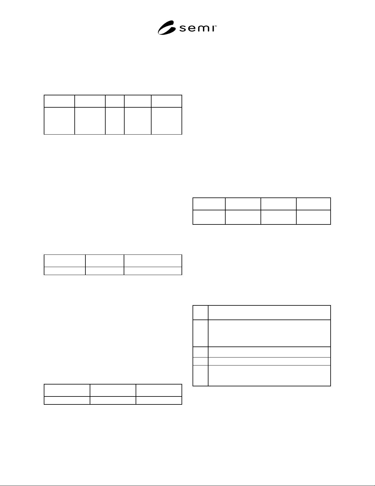
Attribute Definition Rqmt Access Form
The formal
text name of
the attribute
Description
of the
information
contained
Y or N RO or RW (see below)
5.3.1 The access column uses RO (read only) or RW
(read and write) to indicate the access that users of
object services have to the attribute.
5.3.2 A ‘Y’ or ‘N’ in the requirement (rqmt) column
indicates if this attribute must be supported in order to
meet fundamental compliance for the service.
5.3.3 The form column is used to indicates the format
of the attribute. See Section 4.2 for definitions.
5.4 Service Message Representation
5.4.1 Service Resource Definition — The service
resource definition table defines the specific set of
messages for a given service group, as shown in the
following table:
Service Type Description
Message name N or R The intent of the service
5.4.1.1 Type can be either notification (N) or request
(R). Notification messages are initiated by the service
provider. No response is expected. Request messages
are initiated by the service user. Request messages ask
for data or for an operation to be performed. Request
messages expect a specific response (no presumption
on the message content).
5.4.2 Service Parameter Dictionary — Each parameter
should relate to either attributes from the object model
or events of the dynamic model (Harel State Chart). All
parameters to the services are listed in a single table or
dictionary. The column headings for this parameter
dictionary are as follows:
Parameter Description Form
Parameter X Data type A parameter
5.4.2.1 A row is provided in the table for each
parameter of the service. The first column contains the
name of the parameter. This is followed by columns
describing the form and the contents of the parameter.
5.4.2.2 The description column describes the meaning
of the parameter and interrelationships with other
parameters.
5.4.2.3 The form column is used to indicate the type of
data contained in the parameter (see Section 4.2 for
definitions) and the possible values it may take on.
5.4.2.4 To prevent definition of numerous parameters
named “XxxList,” this document adopts the convention
of referring to the list as “(list of) Xxx.” In this case,
the definition of the parameter “Xxx” will be given, not
of the list. Where a list is used in both the request and
the response, the list order in the request is retained in
the response. A list must contain at least one element
unless zero elements are specifically allowed.
5.4.3 Service Message Definition — There is a table for
each service showing the parameter detail. The column
headings for the service detail are as follows:
Parameter Req/ Ind Rsp/ Cnf Comment
Parameter X (see below) (see below) A description
of the service
5.4.3.1 The columns labeled req/ind and rsp/cnf link
the parameters to the direction of the message. The
message sent by the initiator is called the “request”
(req). The receiver terms the message the “indication”
(ind). The receiver may then send a “response” (rsp),
which the original sender terms the “confirmation”
(cnf).
5.4.3.2 The request (req/ind) and response (rsp/cnf)
entries can take on the following values:
“M” Mandatory parameter — Must be given a valid
value.
“C” Conditional parameter — May be defined in some
circumstances and undefined in others. Whether a
value is given may be completely optional or may
depend on the value of another parameter.
“U”
User-defined parameter
“-” The parameter is not used.
“=” The entries M and C in the response can be modified
with (=) to indicate that the value in the response must
match the request.
6 Overview
6.1 Event reporting provides a dynamic and flexible
means by which the service user can receive
notification of events and data relating to objects
defined here and in other SEMI standards.
SEMI E53-0704 © SEMI 1996, 2004 4
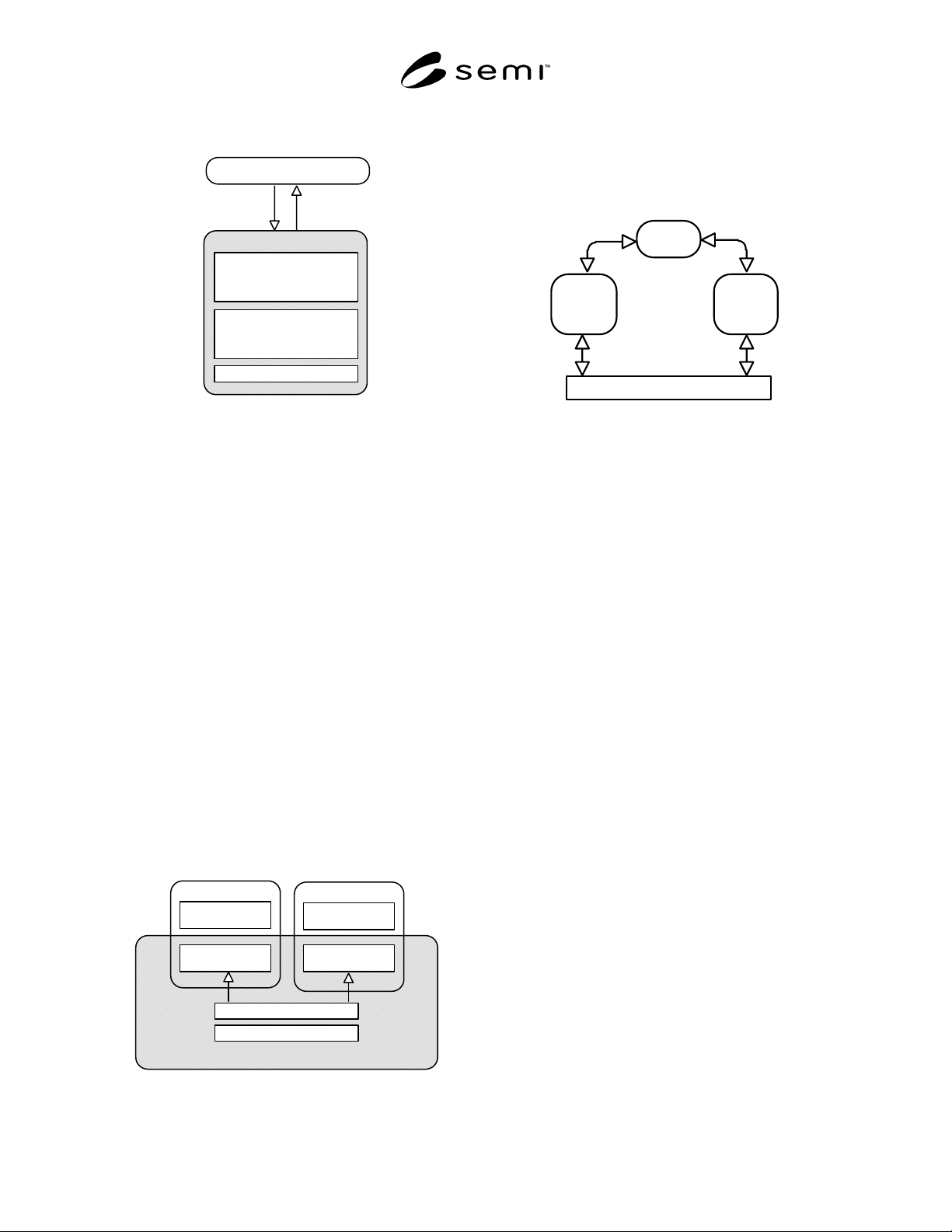
6.2 Figure 1 illustrates a simple event reporting
situation.
Provider
User Defined Confi
g
uration
- Trace Reports
- Data Re
p
orts
- Links to Event Reports
Provider Defined Confi
g
uration
- Trace Reports
- Data Re
p
orts
- Links to Event Reports
Collection Events & Data
User
Request
Notification
Figure 1
Simple Event Reporting
6.3 Event and variable identifiers may be defined by
another standard with which equipment or an object
complies. In either case, the definitions must be
included in the documentation from the supplier.
6.4 The service user may define and access data reports
using the event reporting request services. Data reports
are sampled and sent by the service provider using the
event reporting notification services.
6.5 Data reports may be pre-defined by the supplier.
Such reports cannot be deleted and their report
identifiers may not be used for dynamically created
reports.
6.6 Multiple Service Users — In a more complex
situation, several service users may require
simultaneous access to the event reporting services
(ERS). In this case, the service provider manages data
report definitions independently for each service user as
shown in Figure 2. A copy of each pre-defined report is
made for each service user. Support for more than one
simultaneous service user is optional.
Provider
Collection Events & Data
Provider Defined Confi
g
uration
User Defined
Confi
g
uration
Provider Defined
Confi
g
uration Co
py
User Defined
Confi
g
uration
Provider Defined
Confi
g
uration Co
py
User
User
Figure 2
Multiple Service Users
6.7 Using Object Services — An event reporting
service user can create reports dynamically by
accessing attribute information using the object services
(see SEMI E39) when they are provided (see Figure 3).
User
Object
Services
Provider
Event
Re
p
ortin
g
Provider
Collection Events and Data
Figure 3
Using Object Services
7 Concepts
7.1 Objects and Identifiers — Much of the discussion
and specification for event reporting services relies on
an understanding of object technology and modeling
techniques. The use of object technology for ERS
implementations is not required. Further, it is not
required that ERS implementations be compliant to the
Object Services Standard (OSS). This standard does
specifiy mechanisms by which ERS can take advantage
of OSS when those services are provided.
7.1.1 Events are associated with an object and data is
stored in object attributes. To uniquely identify an event
or an attribute the object to which it relates must first be
identified.
7.1.2 An object may be a physical entity such as stand-
alone process equipment, a cluster tool or a cluster
module. An object may be an abstraction such as a
recipe, a process job or a transfer job. An object may be
defined by the equipment supplier, or by a standard
with which the equipment complies. An example of a
cluster tool, containing process modules, is used in this
section as the service provider. This example is for
illustration purposes only. The same concepts apply for
all factory objects as defined above.
7.1.3 Objects may be part of an object hierarchy or
contained in other objects. The default object is the
object which provides the service connection. In the
case for batch processing equipment which is compliant
to GEM, SEMI E30, the connection to the host is
provided by the equipment and the equipment is the
default object. Also, a cluster controller would be the
default object of equipment containing process
modules. However, from the point of view of the
cluster controller, each connection to the service
SEMI E53-0704 © SEMI 1996, 2004 5
providers in each connected module would be the
default object. For example, the processing
management service of PM:ETCH would be a default
object for that module connection. But, the cluster
controller would have differernt default objects on each
of its other service connections.
7.1.4 An object specifier, (see SEMI E39), identifies an
object within the scope of the service provider. An
object specifier consists of one or more object type and
object instance identifier pairs. For example,
“PM:ETCH>” might be the object specifier of a process
module (type=PM, identifier=ETCH) within a cluster
tool. If the object specifier is omitted, then the default
object is assumed.
7.1.5 Objects are considered local to the service
provider even if they exist on a remote module. That
means the service provider is responsible for detecting
events and accessing data from those objects in a timely
manner, by whatever means, to provide the specified
services.
7.1.6 Equipment which implements OSS-compliant
event reporting services allows the service user to
reference equipment components by an object specifier;
for example, “PM:ETCH>MFC:CCL4.”
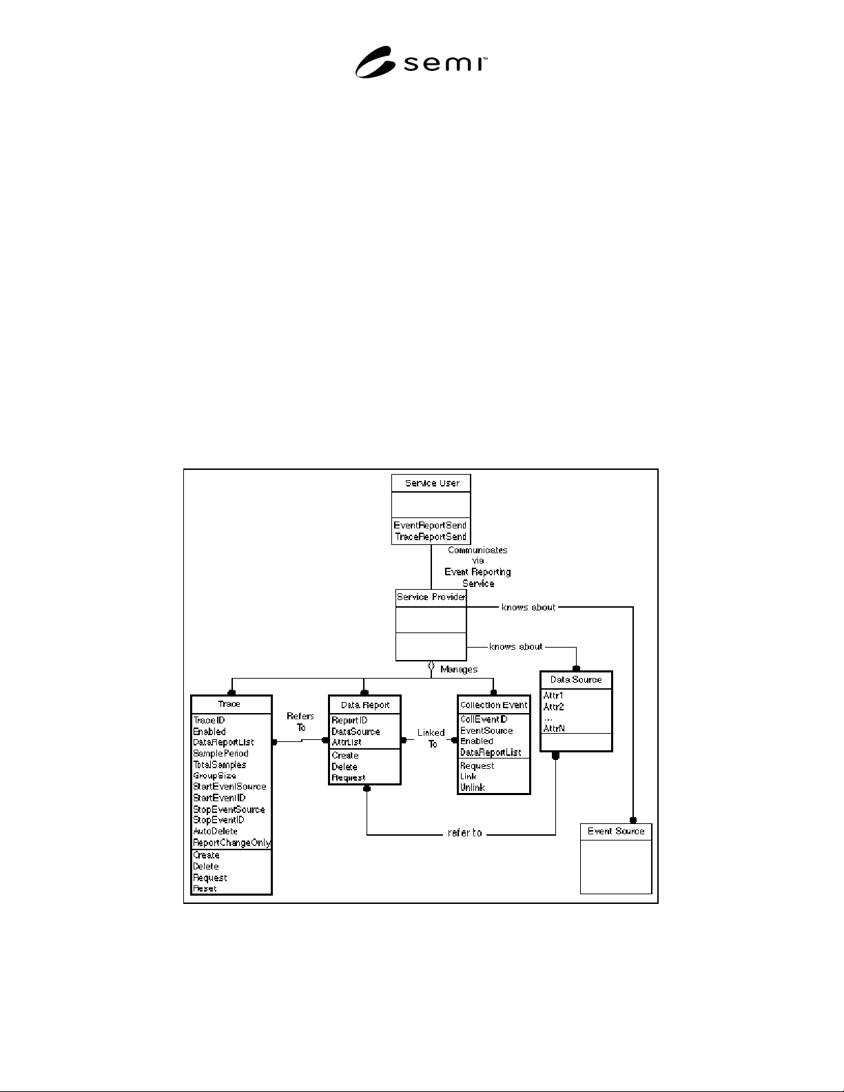
7.2 Event Report Object Model — Figure 4 shows the
objects, attributes (variables), and relationships
involved in event reporting. The notation used is
defined in Section 5. The diagram illustrates the
relationships between the service’s messages and
attributes (variables). The objects and their attributes
are defined Section 8. Only the trace, data report,
collection event, and data source objects’ attributes and
behaviors are standardized in that section. Note that this
model presents a view of event reporting services from
the perspective a single user. It is optional for the
service provider to support simultaneous access from
multiple service users. But for that option the provider
shall present this view to each user independently.
Figure 4
Event Report Object Model