semi合集-English.pdf - 第841页
coefficient measured at th e output of the m atching network, when the inp ut of the network is terminated with both an op en and a short circuit, shall va ry less than five percent in magnitude an d phase at the harmoni…

7.5.6 The output power spectrum of a generator shall
have harmonic content of –40 dB or less when operated
into a load impedance with a reflection coefficient of at
least 0.33 at any phase angle (VSWR of at least 2.0)
from 10% to 100% of the maximum rated output
power.
7.5.7 The generator output circuit shall be provided
with high VSWR protection.
7.5.8 The transient response of the generator operating
into a nominal 50-ohm load shall be provided as a
function of the change in set point, including the time
delay between the request for power (RF enable signal)
and the start of the RF output signal. Data for set point
changes from zero power to full power and back to zero
power as well as set point changes in increments of
33% of full scale shall be provided. For example, data
for a 1 kW generator would include changes from 0 W
to 1000 W, 1000 W to 0 W, 0 W to 333 W, 333 W to
667 W, 667 W to 1000 W, 1000 W to 667 W, 667 W to
333 W, 333 W to 0 W. SEMI E135 or an equivalent
test method(s) shall be used to determine the transient
response of the RF generator.
7.5.9 The ramp rate for power changes shall be
provided in terms of W/second over the power range of
the generator.
7.6 RF Applicator/Interface
7.6.1 The RF applicator/interface (the driven electrode
or the coil/antenna) shall be designed, built, and
maintained to provide a high degree of process
repeatability. The RF impedance that the
applicator/interface presents to the matching network
must have minimal variation in order to maintain
consistent process conditions. A minimum requirement
for consistent operation is for the capacitance between
the interface and ground and the inductance (for
coil/antenna systems) to vary less that 1.5% through
maintenance cycles, during operation and over the
expected lifetime of the applicator/interface.
7.6.2 The frequency response of the RF
applicator/interface (chuck assembly or coil/antenna)
shall be measured to determine the resonance frequency
of the assembly up to 10 times the fundamental
frequency. If possible, the frequency response should
be measured at the operating temperature of the
assembly. The increment of the frequency step shall be
no greater than 4% of the fundamental frequency (e.g.,
for 13.56 MHz, incremental frequency step = 0.54
MHz). The data shall be presented in tabular form in
terms of the reflection coefficient magnitude and phase
angle. An example of tabular data is given in Table 2
and a graphical example is shown in Figures 5 and 6.
7.6.3 For wafer chuck assemblies, the DC leakage
current shall be measured to determine the deterioration
of the dielectric coating over time. Increased leakage
current will flow if the water that cools the chuck has a
low resistivity or if the anodization or other dielectric
coating has deteriorated.
7.6.4 The RF plasma environment within the tool is a
charged environment that alters the charge level on the
product being processed. The RF power delivery
system, in conjunction with the chamber hardware,
shall be compatible with the user-specified sensitivity
level(s) per SEMI E78.
7.7 Tuning and Matching Control Circuits
7.7.1 Automated matching networks require sensing
circuits to determine how to drive their tuning elements
in order to reach a matched condition. The
performance of these control circuits and the error
signals they generate are critical to the proper function
of the matching network. For those networks that are
designed to match to a nominal 50 ohm input
impedance, the matching network input impedance
magnitude shall be 50 3.3 ohms with a phase angle of
3.8° when the automatic matching algorithm has
driven the matching network to achieve a matched
condition.
7.7.2 The sensing circuits in a generator and an
automated matching network shall ensure that the
control signals are insensitive to power in the
harmonics of the drive frequency. For example,
additional filtration (low pass or band pass filters) can
be added to the sensing circuit to achieve this goal.
7.8 RF System Tests
7.8.1 The output power spectrum of a generator shall
have a harmonic frequency content of 40 dB or less
when operated into a matched system (matching
network plus test load) that contains a load impedance
with a Q of at least 10. In other words, the magnitude
of reactive part of the load must be at least ten times
greater than the real part of the load (e.g., 2 – j20
ohms). The cable assembly used during testing shall
nominally be the specific type to be used between the
output of the generator and the input of the matching
network.
7.8.2 To reduce variation between matching networks
on those systems that have multiple RF frequencies
(i.e., one frequency for the source and another
frequency for the bias), the frequency response of the
matching network at the other operating frequencies
and at the harmonics of the other frequencies shall be
repeatable between networks (of the same type/model)
up to the 5th harmonic frequency (inclusive). Over the
expected operating range of the network, the reflection
SEMI E113-1104 © SEMI 2001, 2004 6

coefficient measured at the output of the matching
network, when the input of the network is terminated
with both an open and a short circuit, shall vary less
than five percent in magnitude and phase at the
harmonic frequencies. Comparisons between networks
shall be made at three operating points, which include a
nominal operating point (e.g., at the midpoint of the
tuning range), a point within 10% of the maximum of
the tuning range, and a point within 10% of the
minimum operating range. Unless specifically
designed to, power dissipation in the network greater
than 10% (reflection coefficient of 0.95) at the
harmonic frequencies shall be avoided.
7.8.3 On those systems that have multiple RF
frequencies (i.e., one frequency for the source and
another frequency for the bias), the sensing circuits in
an automated matching network and the rf generators
shall ensure that the control signals are insensitive to
power in the other system frequencies and the
harmonics of all the system frequencies.
7.8.4 The supplier shall provide system verification
hardware (i.e., test fixtures/interfaces) for system
verification after assembly and delivery. Nominally,
this hardware shall be in the form of a nominal coaxial
connector interface (e.g., type “N” connector) for ease
of measurement. Example fixtures would include those
for interfacing with the RF applicator/interface (i.e.,
chuck assembly or coil input) and the output of the
matching network. The supplier shall provide
recommended test methods and/or procedures for
system verification.
8 Related Documents
8.1 IEEE Standards
3
IEE-STD-572 — IEEE Standard for Qualification of
Class 1E Connection Assemblies for Nuclear Power
Generating Stations
IEEE C95.1 — IEEE Standard for Safety Levels with
Respect to Human Exposure to Radio Frequency
Electromagnetic Fields, 3 kHz to 300 GHz
8.2 Federal Communications Commission (FCC)
4
FCC 47CFR1.1310 — Radio frequency radiation
exposure limits
FCC 47CFR2 Part 2 — Frequency Allocations and
Radio Treaty Matters; General Rules and Regulations
3 Institute of Electrical and Electronics Engineers, IEEE Operations
Center, 445 Hoes Lane, P.O. Box 1331, Piscataway, New Jersey
08855-1331, USA. Telephone: 732.981.0060; Fax: 732.981.1721
website: www.ieee.org
4 United States Federal Communications Commission, 445 12th St.
S.W., Washington DC 20554, Website: www.fcc.gov
FCC 47CFR2 Part 2 Subpart J — Equipment
Authorization Procedures
8.3 MIL-Specifications
5
MIL-PRF-31031A — General Specification for
Connectors, Electrical, Plugs and Receptacles, Coaxial,
Radio Frequency, High Reliability, for Flexible and
Semirigid Cables
MIL-STD-348A — Radio Frequency Connector
Interfaces for MIL-C-3643, MIL-C-3650, MIL-C-3655,
MIL-C-25516, MIL-C-26637, MIL-PRF-39012, MIL-
PRF-49142, MIL-PRF-55339, and MIL C-83517
MIL-DTL-28875A — General Specification for
Amplifiers, Radio-Frequency and Microwave, Solid-
State
MIL-T-28732C — General Specification for
Transformer, Impedance Matching, Balanced to
Unbalanced (Balun)
MIL-STD-220B — Test Method Standard: Method of
Insertion Loss Measurement
8.4 International Emissions Standards
FCC CFR47 Part 18 — Industrial, Scientific and
Medical (ISM) Equipment (United States)
4
DIN EN 55011 — Industrial, scientific and medical
(ISM) radio-frequency equipment - Radio disturbance
characteristics - Limits and methods of measurement
6
V-2/97.04 — Regulations for Voluntary Control
Measures
7
CNS 13438 — Limits and Methods of Measurement of
Radio Disturbance Characteristics of Information
Technology Equipment
8
NOTICE: Unless otherwise indicated, all documents
cited shall be the latest published versions.
5 Naval Publication and Forms Center, 5801 Tabor Avenue,
Philadelphia PA 19120 U.S.A Available from website:
www.dodssp.daps.mil/products.htm
6 Available from Deutches Institut für Normung e.V., Beuth Verlag
GmbH, Burggrafenstrasse 4-10, D-10787 Berlin, Germany, website:
www.din.de
7 Voluntary Control Council for Interference by Information
Technology Equipment, website: http://www.vcci.or.jp
8 Chinese National Standards, Available from NSSN
(http://www.nssn.org) as Document CNS C6035700
SEMI E113-1104 © SEMI 2001, 2004 7
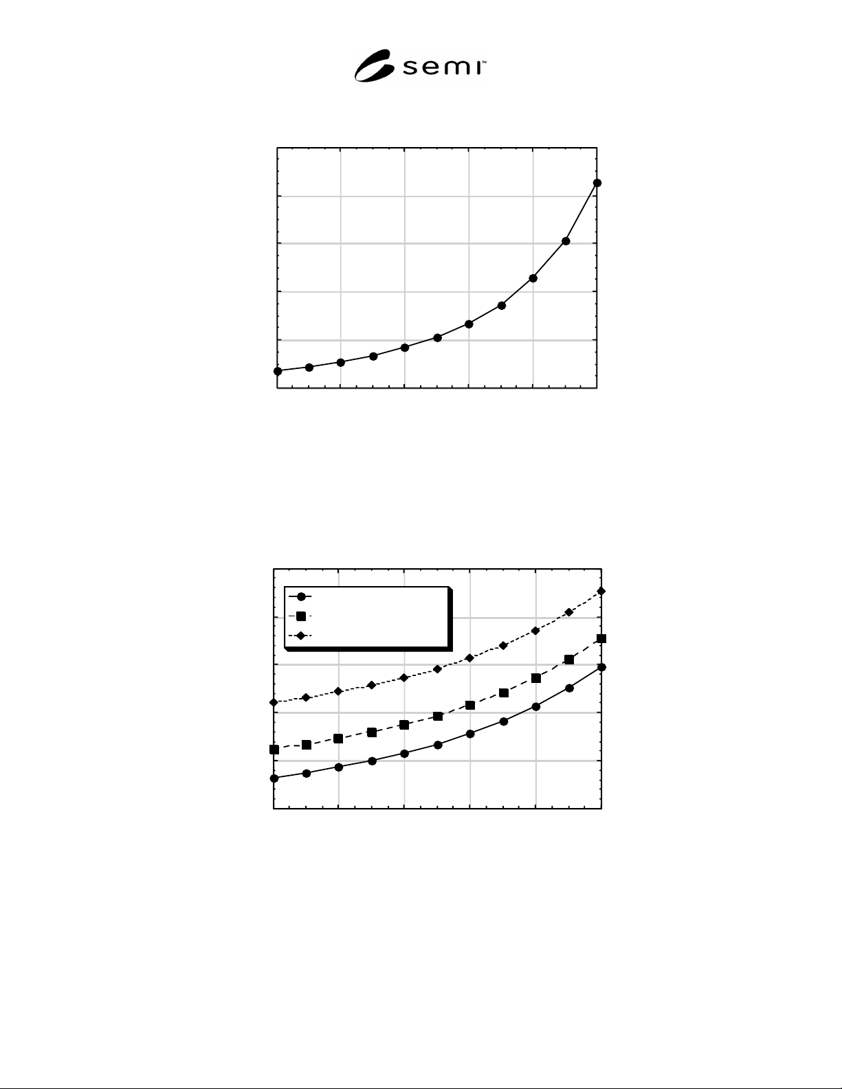
0.0
2.0
4.0
6.0
8.0
10.0
0246810
Real Load Impedance (ohms)
Load Position (volts)
Tune Position Fixed at 5.0 Volts
NOTE: For this example, the full-scale voltage for both the Tune and Load Positions is 10 V (i.e., Tune = 5.0 V corresponds to
50% of full scale).
Figure 1
Example Plot of the Real Part of the Load Impedance as a Function of the Load Position Tuning Element in
the Matching Network
-35.0
-30.0
-25.0
-20.0
-15.0
-10.0
0246810
Tune = 3.0 volts
Tune = 5.0 volts
Tune = 7.0 volts
Reactive Load Impedance (ohms)
Load Position (volts)
NOTE: The Tune Position is at the indicated fixed value for each set of data. For this example, the full-scale voltage for both the
Tune and Load Positions is 10 V (i.e., Tune = 3.0 V corresponds to 30% of full scale).
Figure 2
Example Plot of the Reactive Part of the Load Impedance as a Function of the Load Position Tuning Element
in the Matching Network
SEMI E113-1104 © SEMI 2001, 2004 8