semi合集-English.pdf - 第2080页
SEMI E54.11-0301 © SEMI 2001 3 7 Conventions 7.1 This docum ent embraces the c o n ve ntions a nd notati ons stat ed in section 6 of SEMI E54.1. 8 Device High L evel St ructu r e 8.1 General Description 8.1.1 The h igh-l…

SEMI E54.11-0301 © SEMI 2001 2
However, SEMI E39 has specific requirements that are
intended for higher level applications and thus are not
applied to the Endpoint Device Model.
3.5 Operation over the entire range specified for an
attribute within a specific object is not a requisite for
compliance with this specification.
4 Referenced Standards
NOTE 1: As listed or revised, all documents cited shall be the
latest publications of adopted standards.
4.1 SEMI Standards
SEMI E39 — Object Services Standard: Concepts,
Behavior, and Services
SEMI E54 — Sensor/Actuator Network Standard
SEMI E54.1— Standard for Sensor/Actuator Network
Common Device Model
5 Terminology
5.1 Abbreviations and Acronyms
5.1.1 EP — an EPD sensor named E ndpoint.
5.2 Definitions
5.2.1 Endpoint Device (EPD) — a self-contained
device, consisting of device specific signal-processing
electronics, which is capable of monitoring and
measuring the occurrence of a process endpoint.
5.2.2 Endpoint Detection Event — consists of the
device operation of monitoring, measuring, analyzing,
waiting, and reporting endpoint.
5.3 This document inherits the terminology defined by
SEMI E54.1
5.3.1 Attribute
5.3.2 Behavior
5.3.3 Boolean (BOOL)
5.3.4 Byte
5.3.5 Character
5.3.6 Common Device Model (CDM)
5.3.7 Data Type
5.3.8 Data Units
5.3.9 Device
5.3.10 Device Manager (DM) Object
5.3.11 Device Model
5.3.12 Double Integer (DINT)
5.3.13 Enumerated Byte
5.3.14 Full Scale Range
5.3.15 Instance
5.3.16 Last Valid Value (LVV)
5.3.17 Long Integer (LINT)
5.3.18 Long Real (LREAL)
5.3.19 Manufacturer
5.3.20 Nibble
5.3.21 Null Character
5.3.22 Object
5.3.23 Real (REAL)
5.3.24 S, A, and C Objects
5.3.25 Sensor Actuator Controller (SA C) Object
5.3.26 Service
5.3.27 Signed Integer (INT)
5.3.28 Short Integer (SINT)
5.3.29 State Diagram
5.3.30 Test String
5.3.31 Unsigned Double Integer (UDINT)
5.3.32 Unsigned Double Long Integer (UDLINT)
5.3.33 Unsigned Integer (UINT)
5.3.34 Unsigned Long Integer (ULINT)
5.3.35 Unsigned Short Integer (USINT)
6 Requirements and Specifications
6.1 In order to implement this standard in an Endpoint
Device, it is necessary to also implement SEMI E54.1
and one of the Sensor/Actuator Network Communi-
cation Standards (SEMI E54.4–E54.9). See Section 3
for more information on a complete interoperability
standard.
6.2 This specification also require s the implementation
of a Date_And_Time data structure used to represent
the current device Date and Time. Table 1 defines the
format of the Date_And_Time data type.
Table 1 Date_And_Time Format
Data Item Description Range
1 Number of
milliseconds
since midnight
Unsigned Double
Integer (UDINT)
2 Number of days
since 1/1/72
Unsigned Integer
(UINT)
SEMI E54.11-0301 © SEMI 20013
7 Conventions
7.1 This document embraces the c onventions and
notations stated in section 6 of SEMI E54.1.
8 Device High Level Structu re
8.1 General Description
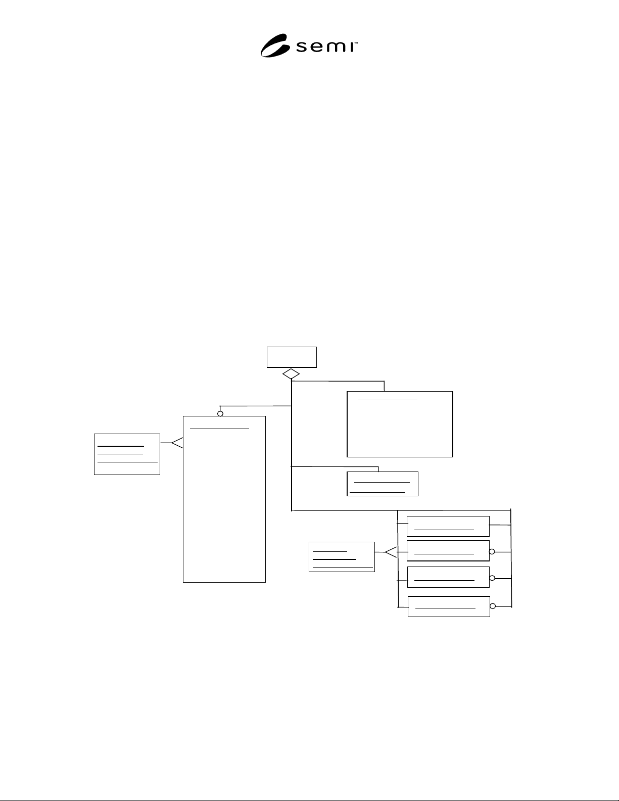
8.1.1 The high-level object view of an Endpoint
Device (EPD) profile is shown in Figure 1.
8.1.2 Note that the profile for an “EP D Device” object
is depicted in Figure 1 only for the purposes of
illustrating a high level view of the device and its
component objects. In the context of this document, this
object is not addressable, does not have addressable
attributes, does not have accessible services and, does
not exhibit any defined behavior.
8.1.3 In the remainder of this section , this document
defines in detail the component objects unique to the
EPD device. References, rather than definitions, are
included for the DM, the SAC and other objects defined
in SEMI E54.1.
8.1.4 Many of the objects defined in this document
inherit properties from other objects. The properties
inherited include attribute, service and behavior
definitions. These other objects are specified here or in
SEMI E54.1.
8.1.5 This document provides for future extensions as
well as manufacturer specific enhancements by
reserving object attribute identifiers and object service
identifiers. Specifically all object definitions in this
document specify or reserve the first 64 attribute
identifiers (A1 through A64) and the first 64 service
identifiers (S1 through S64) allowing manufacturers to
specify identifiers beyond these ranges. Additionally,
byte enumerated attributes are specified or reserved
from 0 to 63 allowing manufacturers to specify an
enumeration beyond this range (64 to 255).
8.1.6 Endpoint Device (EPD) Description — An
Endpoint device profile is composed of the component
objects and object relationships shown in Figure 1.
1+
EPD
Sensor-BI-TH-EP
Maximum Time
Sensor-BI-TH
(see Note 1)
(defined in CDM)
SAC (See Note 1)
Number of Endpoint Objects
-----------
DM (See Note 1)
Assembly
(see Note 1)
(defined in CDM)
Assembly-EPD#1
Assembly-EPD#2
(See
N
ote 2)
Elapsed Time
Time Stamp
-----------
Endpoint On
Endpoint Off
Endpoint Start
Recipe Number
(defined in CDM)
Assembly-EPD#3
Endpoint Suspend
Endpoint Resume
Reset Endpoint
Minimum Time
Target Time
Step Number
Download Recipe
Upload Recipe
Calibrate
Assembly-EPD#4
Figure 1
Endpoint Device High Level Structure
NOTE 1: The Sensor-BI-TH, DM, SAC, and Assembly are defined in the CDM. Additional attributes and services are added to
support the EPD.
NOTE 2: Assembly-EPD #1 object is required. Other Assembly-EPD objects are optional.
SEMI E54.11-0301 © SEMI 2001 4
8.1.7 General Requirements
8.1.7.1 Device Objects — All objects are defined in terms of their object name and Class/Object identifier.
Identifiers for all objects described in this document are summarized in Table 2.
Table 2 Endpoint Device Objects
Referenced
Document
Section
Object Name Class/Object
Identifier
Minimum # Maximum #
8.2 Device Manager
(DM)
EPD1 1 1
8.3 Sensor Actuator
Controller (SAC)
EPD2 1 1
8.5 Sensor-BI-TH-EP EPD3 1 1024
8.6 Assembly-EPD#1 EPD4 1 1
8.6 Assembly-EPD#2 EPD5 0 1
8.6 Assembly-EPD#3 EPD6 0 1
8.6 Assembly-EPD#4 EPD7 0 1
— Reserved EPD7 – EPD63 - —
— Manufacturer
Specified
> EPD64 - —
8.1.7.2 Object Services — Not all object services listed in this document can necessarily be requested over the
network. They are included in this document because their behavior may generate network activity.
8.1.7.3 Object Behavior — A network specific service error response is generated for all service requests received
over the network that are not supported by the object, or contain a parameter value which is beyond the supported
range, or which is otherwise invalid.
8.2 Device Manager Object (DM) — The Device Manager object is the device component responsible for
managing and consolidating the device operation as specified in SEMI E54.1. The following sections specify the
components of the DM object that are not specified in the Common Device Model or require further definition than
specified in SEMI E54.1.
8.2.1 Device Manager Object Attributes — Required and optional DM object attributes are listed in Table 3.
Table 3 DM Object Attributes
Attribute Name Attribute
Identifier
Access
Network
Required Form
Device Type A1 R Yes Refer to SEMI E54.1.
Exception Detail Alarm A13 R No Refer to SEMI E54.1.
Exception Detail Warning A14 R No Refer to SEMI E54.1.
Reserved A33-A64 — — Reserved for SDM future expansion
Manufacturer Specified > A64 — — Manufacturer Specific attributes
8.2.1.1 Device Type — An attribute th at uniquely identifies the type of the device on the network. The device type
attribute is assigned as follows:
Endpoint Device = “EPD”
NOTE 2: If the “Endpoint Device” functionality is implemented by another Sensor/Actuator Network Specific Device Model, the
‘Device Type’ attribute value may be specified by the manufacturer to identify the other Specific Device Model.
8.2.1.2 Exception Detail Alarm (Optional) — An attribute that identifies the detailed alarm status of the device.
Table 4 defines the bit assignments associated with the alarm exception detail.