semi合集-English.pdf - 第6426页
SEMI G75.6-069 8 © SEMI 1998 2 6.5 Calculation 6.5.1 The shrinkage factor, A (%), is d eter mined from the following equatio n: A(%) = ( L 1 − L 2 ) × 100 L 1 where : L 1 is the length (mm) of the specimen befor e baki n…
SEMI G75.6-0698 © SEMI 19981
SEMI G75.6-0698
TEST METHOD FOR MEASUREMENT OF THE SHRINKAGE FACTOR
OF LEADFRAME TAPE
1 Summary of Method
1.1 The length of tape samples is measured before and
after exposure to temperatures comparable to those
used in the assembly and packaging of IC. The
shrinkage is calculated as a percentage in the dimension
measured.
2 Equipment
2.1 Magnifying projector with 0.01 mm accuracy
2.2 Circulating air oven capable of 300 ± 2°C
accuracy
2.3 Cutting die for sample preparation
2.4 Thermohygrostat
2.5 Straight edge
2.6 Scribing tool
3 Sampling
3.1 The sampling is one sample per one lot. The
vendor must report the definition of lot, if the customer
requires it.
4 Preparation of Specimens
4.1 Cut specimens out of the samples using the cutting
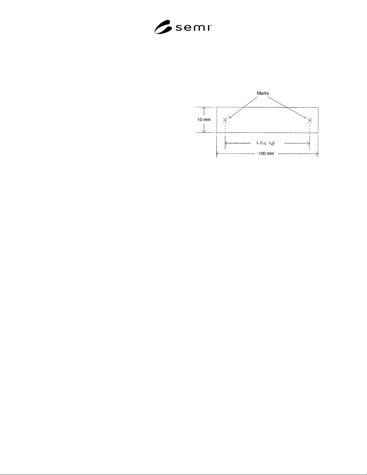
die. The specimen shall be 100 ± 1.0 mm long and 10 ±
1.0 mm wide.
4.2 Allow the specimen to be stabilized at 23° ± 2°C
and 50 ± 5% RH for 16 hours minimum. This may be
carried out in a climate controlled room or in a
thermohygrostat.
4.3 Using the straight edge and scribing tool, scribe
marks on the specimens as shown in Figure 1. The
marks shall be parallel to each edge of the specimen,
and the distance to be measured, L, shall be parallel to
the long side of the specimen. The mark shall be
located within 5 mm of the ends of the specimen.
Figure 1
Size of a Marked Specimen
5 Test Conditions
5.1 Baking Condition 1 — 100°C for 60 ± 1 minute.
5.2 Baking Condition 2 — 200°C for 60 ± 1 minute.
5.3 Baking Condition 3 — 300°C for 10 ± 0.5
minutes.
NOTE: Alternate temperatures may be used by agreement
between vendor and customer.
6 Procedure
6.1 Place a specimen between the glass plates of the
magnifying projector and measure the length, L
1
,
between two marks (see Figure 1). Repeat this
measurement for all specimens.
6.2 Place the specimen in the oven at the appropriate
test condition.
6.3 Remove the specimens from the oven and store at
23° ± 2°C and 50 ± 5% RH for 16 hours minimum.
6.4 Place the specimens between t he glass plates of the
magnifying projector and measure the new length, L
2
,
between two marks used in Section 6.1.

SEMI G75.6-0698 © SEMI 1998 2
6.5 Calculation
6.5.1 The shrinkage factor, A (%), is determined from
the following equation:
A(%)
=
(L
1
−
L
2
)
×
100
L
1
where
:
L
1
is the length (mm) of the specimen
before baking
L
2
is the length (mm) of the specimen
after baking
7 Related Documents
NOTE: As listed or revised, all documents cited shall be the
latest publications of adopted standards.
7.1 JIS Specification
1
JIS K 6911 — Testing Methods for Thermosetting
Plastics
NOTICE: These standards do not purport to address
safety issues, if any, associated with their use. It is the
responsibility of the user of these standards to establish
appropriate safety and health practices and determine
the applicability of regulatory limitations prior to use.
SEMI makes no warranties or representations as to the
suitability of the standards set forth herein for any
particular application. The determination of the
suitability of the standard is solely the responsibility of
the user. Users are cautioned to refer to manufacturer’s
instructions, product labels, product data sheets, and
other relevant literature respecting any materials
mentioned herein. These standards are subject to
change without notice.
The user’s attention is called to the possibility that
compliance with this standard may require use of
copyrighted material or of an invention covered by
patent rights. By publication of this standard, SEMI
takes no position respecting the validity of any patent
rights or copyrights asserted in connection with any
item mentioned in this standard. Users of this standard
are expressly advised that determination of any such
patent rights or copyrights, and the risk of infringement
of such rights, are entirely their own responsibility.
1 Japanese Standards Association, 1-24, Akasaka 4 Chome, Minato-
ku, Tokyo, Japan
Copyright by SEMI® (Semiconductor Equipment and Materials
International), 3081 Zanker Road, San Jose, CA 95134. Reproduction o
f
the contents in whole or in part is forbidden without express written
consent of SEMI.
SEMI G75.7-0698 © SEMI 19981
SEMI G75.7-0698
TEST METHOD FOR MEASUREMENT OF THERMAL DECOMPOSITION
TEMPERATURE OF LEADFRAME TAPE AND ADHESIVE
1 Summary of Method
1.1 A thermogravimetric (TG) analyzer is used to
monitor the weight of a tape sample as the temperature
increases to 700°C. It should be made to measure the
leadframe tape or the base film and the adhesive
separately. The results are obtained as a plot of Weight
Retention versus Temperature, from which the thermal
decomposition temperature for both the base film and
the adhesive may be obtained.
2 Equipment
2.1 Thermogravimetric (TG) analyzer capable of 0.01
mg accuracy.
2.2 Thermohygrostat
3 Sampling
3.1 The sampling is one sample per one lot. The
vendor must report the definition of lot, if customer
requires it.
4 Preparation of Specimens
4.1 Allow the samples to be stabilized at 23 ± 5°C and
50 ± 5% RH for 16 hours minimum. This may be
carried out in a climate controlled room or in a
thermohygrostat.
4.2 Cut specimens from the sample. The specimen
shall weigh 10 to 20 mg.
NOTE 1: The base film before coating with the adhesive can
be used for the test. The vendor has to ship the base film
before coating with the adhesive, if customer requires it.
NOTE 2: The adhesive sample can be obtained by scraping
the adhesive.
5 Equipment Setup and Cal ibration
5.1 Refer to Thermogravimetric Analyzer
manufacturer’s manual for setup and calibration
procedures.
5.2 The ambient in the measurement shall be air.
6 Procedure
The measurement of TG should be made to measure the
leadframe tape or the base film and the adhesive
separately.
6.1 Place the specimen in the platinum vessel.
6.2 Set the thermal ramp to 10 ± 1°C/minute and
maximum temperature to 700°C.
6.3 Repeat for all specimens.
7 Method of Reading TG Cu rve
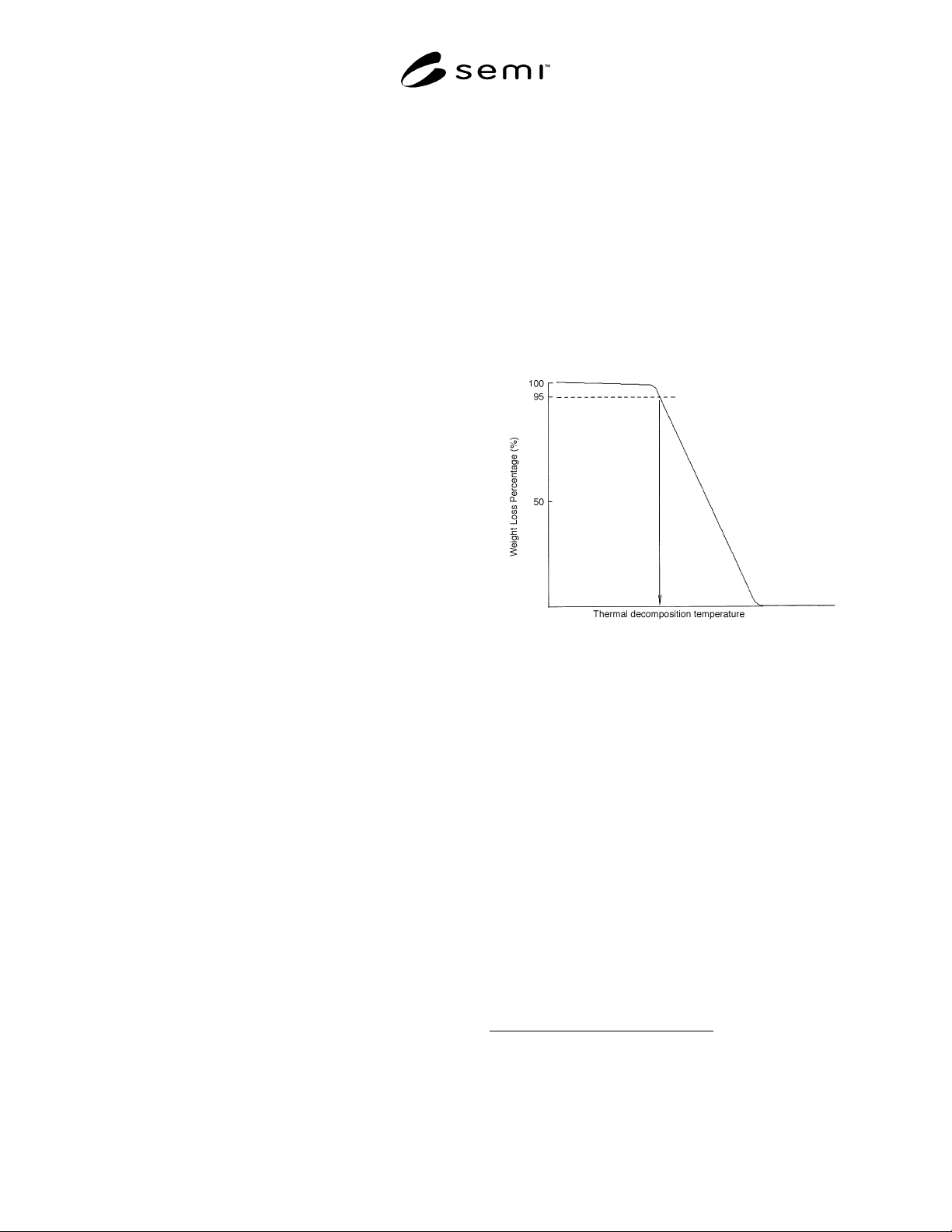
7.1 In Figure 1, the thermal decomposition is
determined by the temperature at 5% of the weight loss.
Figure 1
TG Curve of the Leadframe Tape
8 Related Documents
NOTE: As listed or revised, all documents cited shall be the
latest publications of adopted standards.
8.1 ASTM Specification
1
ASTM D 3850 — Standard Test Method for Rapid
Thermal Degradation of Solid Electrical Insulating
Materials by Thermogravimetric Method
8.2 JIS Specification
2
JIS K 7120 — Testing Methods of Plastics by
Thermogravimetry
1 American Society for Testing and Materials, 100 Barr Harbor
Drive, West Conshohoken, PA 19428-2959
2 Japanese Standards Association, 1-24, Akasaka 4 Chome, Minato-
ku, Tokyo, Japan