semi合集-English.pdf - 第2103页
SEMI E54.13-0303 © SEMI 2003 4 6.6 Transport Lay er The transport layer requires the support of T ransmission Control Protocol (TCP) (R FC 793) as well a s User Datagr am Protoc ol (UDP) (RFC 768). 6.7 Session Layer …
SEMI E54.13-0303 © SEMI 2003 3
5.3.1 As this standard defines the presentation or
mapping of CDM data structure and behavior over a
network, it makes use of many of the terms in the CDM
document. Table 1 provides a mapping of fundamental
terminology of the CDM document into this document
and the EtherNet/IP specification. Note that Column 2
contains an equal sign “=” if the definition is used
exactly as specified in the CDM specification.
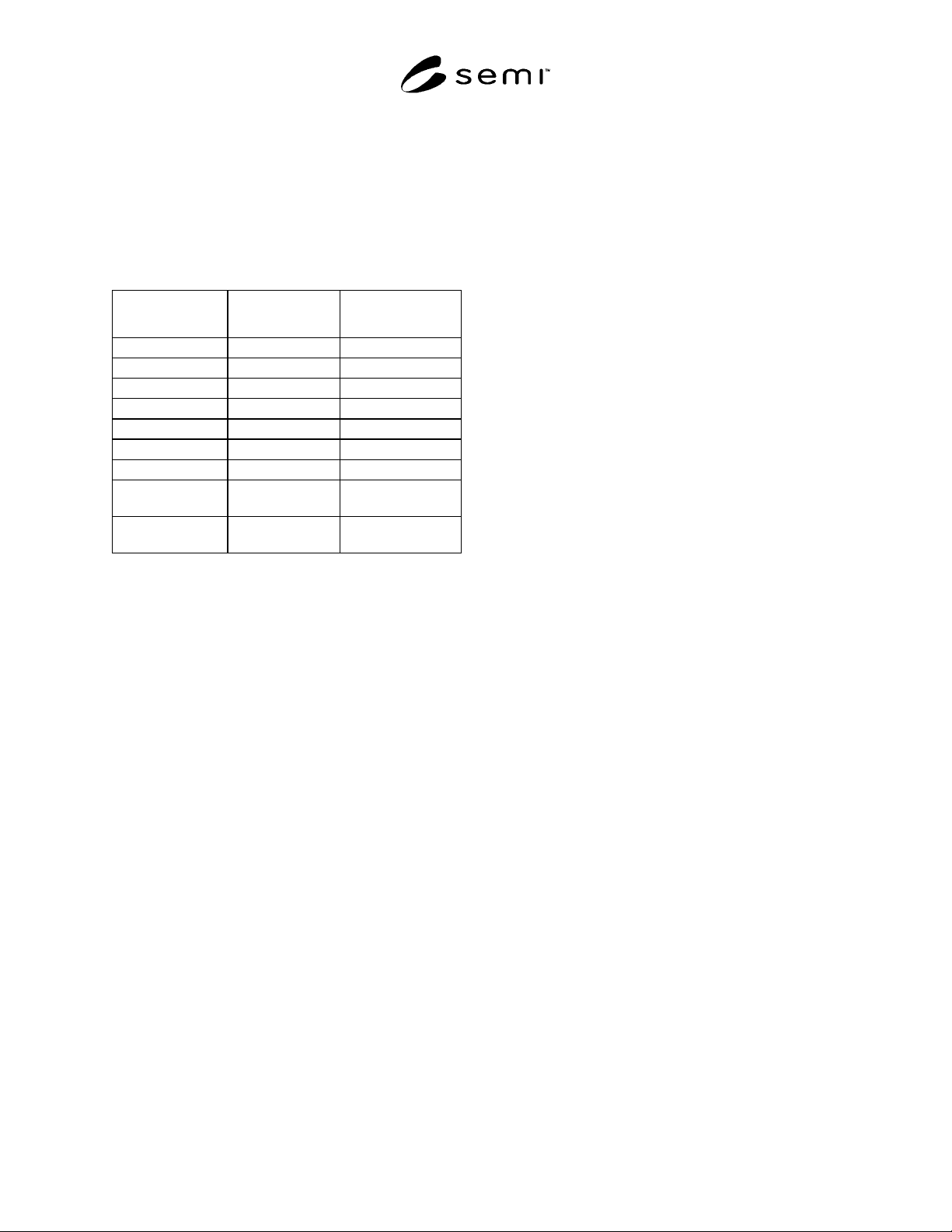
Table 1 Mapping of CDM to NCS Terminology
CDM Term NCS Equivalent EtherNet/IP
Equivalent
Device = =
Device Model = Device Profile
Object =, Class =, Class
Instance = =
Attribute = =
Behavior = =
Service = =
Behavior State
Diagram
= State Transition
Diagram
State Transition
Matrix
= State Event Matrix
5.4 EtherNet/IP Specific Definitions
5.4.1 class A set of objects that all represent the
same kind of system component. A class is a
generalization of an object. All objects in a class are
identical in form and behavior, but may contain
different attribute values.
5.4.2 Control and Information Protocol (CIP) The
common network, transport and application layers
shared by EtherNet/IP and DeviceNet.
5.4.3 device profile An EtherNet/IP specification for
a device that contains an object model for the device
type, the I/O data format for the device type, and the
configuration data and the public interface(s) to that
data.
5.4.4 encapsulation The technique used by layered
protocols in which a layer adds header information to
the protocol data unit (PDU) from the layer above. As
an example, in Internet terminology, a packet would
contain a header from the data link layer, followed by a
header from the network layer (IP), followed by a
header from the transport layer (TCP), followed by the
application protocol data.
5.4.5 Ethernet A 10/100-Mb/s standard for LANs,
initially developed by Xerox, and later refined by
Digital, Intel and Xerox (DIX). All hosts are connected
to the network media where they contend for network
access using a Carrier Sense Multiple Access with
Collision Detection (CSMA/CD).
5.4.6 EtherNet/IP EtherNet/IP (Ethernet/Industrial
Protocol) is a networked communications protocol that
specifies the encapsulation of CIP over TCP/IP.
5.4.7 Explicit Message Connections Connections
over an EtherNet/IP network that provide generic,
multi-purpose communication paths between two
devices. These connections often are referred to as just
Messaging Connections. Explicit Messages provide the
typical request/response–oriented network communica-
tions.
5.4.8 Input/Output Connections Connections over
an EtherNet/IP network that provide dedicated, special-
purpose communication paths between a producing
application and one or more consuming applications.
Application-specific I/O data moves though these ports.
6 Communication Protocol High Level
Structure
6.1 Though the protocol specification is called
“EtherNet/IP”, Ethernet is technically not required.
EtherNet/IP may be used on any media that supports
transmission of the Internet Protocol (IP). When
Ethernet is used, it shall comply with the IEEE 802.3
specification.
NOTE 1: Conformance testing of EtherNet/IP products is
limited to those products implemented on Ethernet.
6.2 The following sections give a brief description of
the EtherNet/IP specification in terms of the seven layer
architecture described by the ISO Basic Reference
Model for Open Systems Interconnection (the OSI
model).
6.3 Physical Layer The physical layer requirements
include specifications for topology, media, connectors,
shielding and grounding. Where copper media is used,
the EtherNet/IP specification is based on the
ANSI/TIA/EIA-568-B Category 5/5E cable/connector
specifications. A Commercial grade and Industrial
grade level of conformance are specified. The
signaling and coupling are as specified in the IEEE
802.3 / TP-PMD standard.
6.4 Data Link Layer For compatibility with
EtherNet/IP conformance testing capabilities, the
device must comply with the Ethernet Data Link Layer
Specifications as specified by IEEE 802.3. Otherwise,
any data link layer that supports the IP is acceptable.
6.5 Network Layer The network layer for the
EtherNet/IP protocol is defined by the Internet Protocol
(IP version 4) (RFC 791).
SEMI E54.13-0303 © SEMI 2003 4
6.6 Transport Layer The transport layer requires the
support of Transmission Control Protocol (TCP) (RFC
793) as well as User Datagram Protocol (UDP) (RFC
768).
6.7 Session Layer Many of the services and
functions of the session layer for the EtherNet/IP
protocol are divided and handled, in varying capacities,
by the TCP/UDP protocol specifications and the
EtherNet/IP Application Layer specifications. The first
defines transport level connection sessions, while the
latter defines application level sessions in terms of
Explicit Connection and I/O Connection management.
6.8 Presentation Layer The presentation layer is
defined in terms of standard data types and specific
encoding definitions for application layer data.
6.9 Application Layer The device shall comply with
the EtherNet/IP application layer specification for
defining and addressing objects, including their
attributes and services, and enabling specified network
behavior. The device shall comply with the object
model specifications provided in the EtherNet/IP
specification.
6.10 Object models EtherNet/IP provides an object-
oriented specification for creating, defining and
addressing objects explicitly, including their attributes
and services (i.e., explicit messaging), and creating,
defining and communicating object attribute assemblies
in an application dependent format (i.e., input/output
messaging). The device shall comply with the object
model specifications provided in the EtherNet/IP
documentation. In addition, the device shall comply
with the object specifications defined in Section 7 of
this document.
7 Required Object Types
7.1 The EtherNet/IP specification identifies and
describes objects (i.e., classes) that must exist in all
EtherNet/IP compliant devices. The Common Device
Model (CDM) specification additionally identifies two
objects, the Device Management (DM) and Sensor
Actuator Controller (SAC) objects, that must exist in all
SEMI compliant SAN devices. The required object
types for a SEMI compliant SAN device utilizing the
network communication specification described herein,
necessarily comprises the union of the above two
requirements.
7.2 A list of required and optional object types is given
in Table 2. Note that the Sensor, Actuator, and
Controller object types are not required, and are
indicated as optional in the CDM specification. These
objects are aggregated together to form a SEMI and
EtherNet/IP compliant device.
7.3 The two required object types from the CDM (the
DM and the SAC) are implemented as mapped
components in EtherNet/IP; they are mapped to the
SEMI-specific S-Device Supervisor object class as
described in this section.
7.4 The listed object types are:
• Identity,
• Message Router (MR),
• Connection (Conn),
• Connection Manager (CM),
• Ethernet Link (EL),
• TCP/IP Interface (TCP/IP),
• S-Device Supervisor (S-DS),
• Device Management (DM),
• Sensor Actuator Controller (SAC),
• Sensor,
• Actuator, and
• Controller.
7.5 Also, although not a network addressable object,
each device shall support the Unconnected Message
Manager (UCMM) as defined by EtherNet/IP.
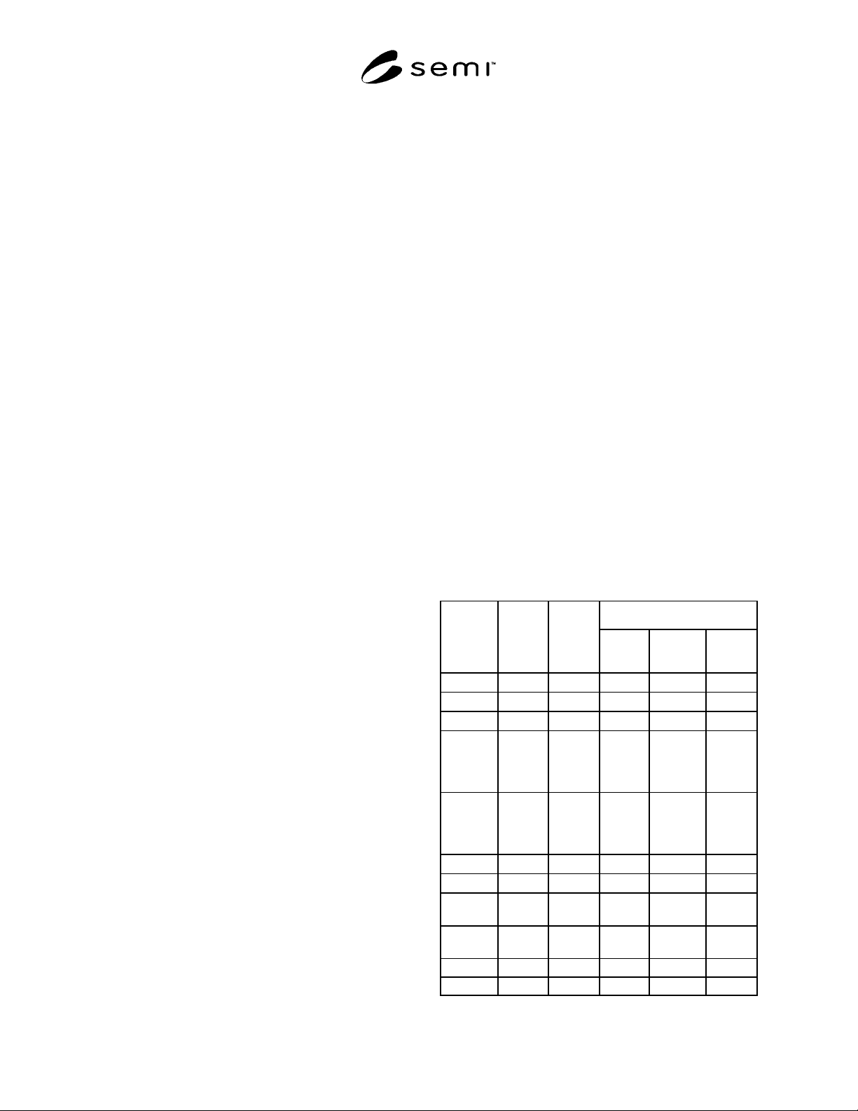
Table 2 Object Types
Required by
Object EIP
Class ID
(See
Note 1.)
CDM
Tag (See
Note 2.)
EIP (See
Note 1.)
CDM (See
Note 2.)
NCS
Identity 01
Yes No Yes
MR 02
Yes No Yes
Conn 05
Yes No Yes
CM 06
Condi-
tional
(See
Note 1.)
No Condi-
tional
(See
Note 1.)
EL F5
Condi-
tional
(See
Note 1.)
No Condi-
tional
(See
Note 1.)
TCP/IP F6
Yes No Yes
S-DS 30
No No Yes
DM
DmI0 No Yes Yes (See
Note 4.)
SAC
SACI0 No Yes Yes (See
Note 4.)
Sensor 31 SenIn No No No
Actuator 32 ActIn No No No
SEMI E54.13-0303 © SEMI 2003 5
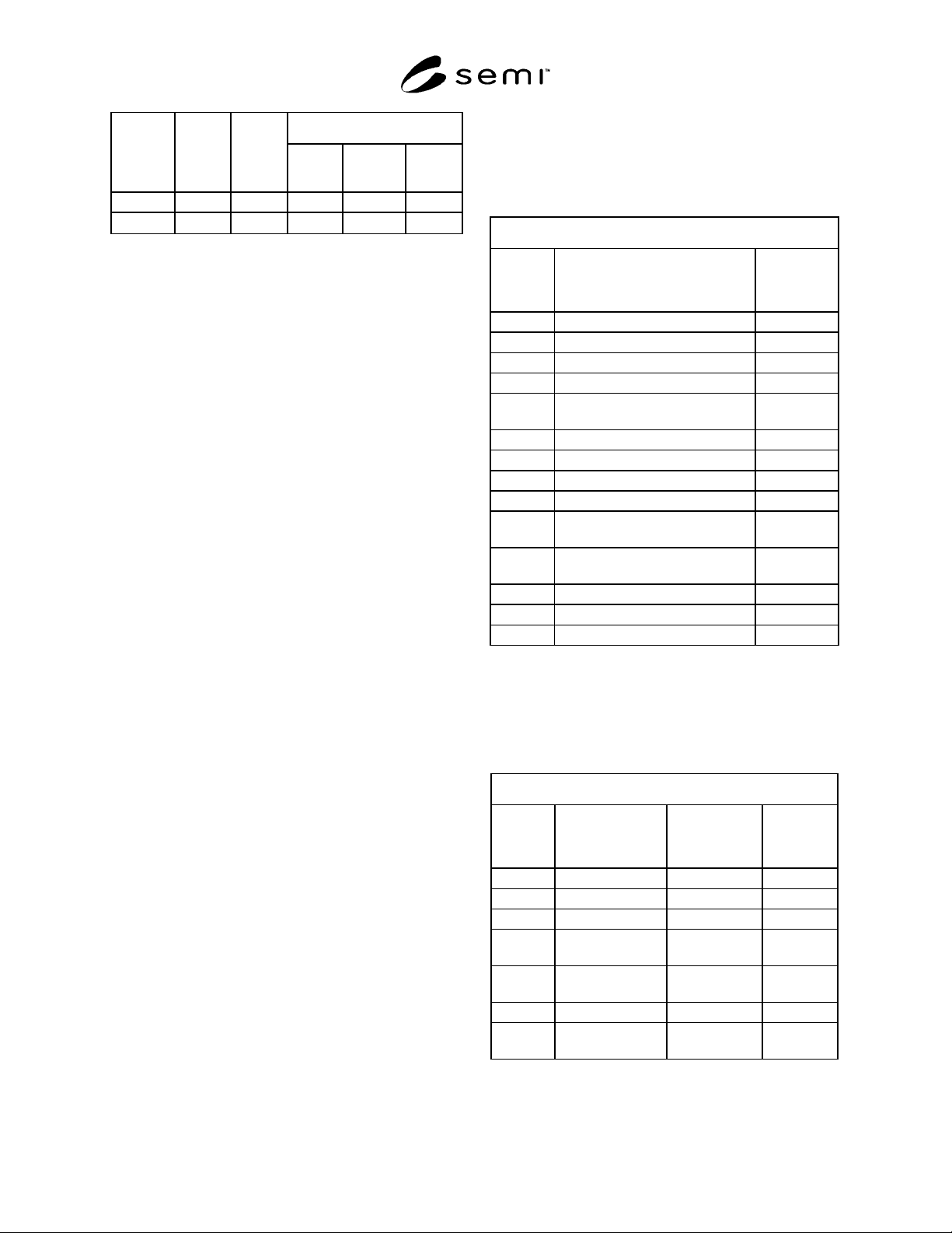
Required by Object EIP
Class ID
(See
Note 1.)
CDM
Tag (See
Note 2.)
EIP (See
Note 1.)
CDM (See
Note 2.)
NCS
Controller 33 CntIn No No No
(Other) ***
No No No
NOTE 1: See EtherNet/IP specification for further information;
values are hexadecimal.
NOTE 2: See CDM specification for further information.
NOTE 3: Application Dependent.
NOTE 4: The DM and SAC Objects are implemented as mappings to
the S-Device Supervisor object for EtherNet/IP.
7.6 See the EtherNet/IP specification for the
implementation detail of the following object classes:
• Identity
• Message Router (MR)
• Connection (Conn)
• Connection Manager (CM)
• Ethernet Link (EL)
• TCP/IP Interface (TCP/IP)
• S-Device Supervisor (S-DS)
7.7 The Sensor, Actuator and Controller object types
are utilized collectively to model the type specific
structure and behavior of the device. The requirement
and number of each of these object types in a device
model is device type specific. Further, the attributes,
services and behavior associated with each of these
object classes and instances in a device is also device
type specific, but must be compliant with both SEMI
and EtherNet/IP specifications. The specification of
these object types for a specific device type can be
found in the appropriate SDM. The method of
presentation of object structure and behavior to the
EtherNet/IP network for objects defined for and
associated with a specific device type can be found in
Section 9 of this document.
7.8 The following sections describe the implementation
detail for the two required objects from the CDM. The
EtherNet/IP specification essentially combines the
Device Management (DM) Object and the Sensor
Actuator Controller (SAC) Object into a single Object:
the S-Device Supervisor (S-DS) Object.
7.9 Device Management (DM) Object The DM
object is the device component responsible for
managing and consolidating the device operation. The
DM object as well as its common required and optional
attributes, services and behavior are described in the
CDM standard. The presentation of object attributes
and services to the EtherNet/IP network shall be as
indicated in Table 3 and Table 4 respectively. Each
attribute and service is shown with its corresponding
identifier (ID) for the S-DS Object.
Table 3 Network Presentation of DM Object
Attributes
Device Management Object Attributes
CDM Tag Name S-DS
Attribute ID
(See Note 1.)
DmA1 Device Type 03
DmA2 Standard Revision Level 04
DmA3 Device Manufacturer Identifier 05
DmA4 Manufacturer Model Number 06
DmA5 Software or Firmware Revision
Level
07
DmA6 Hardware Revision Level 08
DmA7 Serial Number 09
DmA8 Device Configuration 0A
DmA9 Device Status 0B
DmA10 Reporting Mode N.A. (See
Note 2.)
DmA11 Exception Status Timer N.A. (See
Note 2.)
DmA12 Exception Status 0C
DmA13 Exception Detail Alarm 0D
DmA13 Exception Detail Warning 0E
NOTE 1: Attribute Identifier Values are hexadecimal.
NOTE 2: Reporting is controlled in EtherNet/IP by the configuration
of connection related object instances. See the EtherNet/IP
specification for detail.
Table 4 Network Presentation of DM Object
Services
Device Management Object Services
CDM Tag Name (SEMI) Name (S-DS) S-DS
Service ID
(See Note 1.)
DmS1 Reset Reset 05
DmS2 Abort Abort 4B
DmS3 Recover Recover 4C
DmS4 Get Attribute Get_Attribute
_Single
0E
DmS5 Set Attribute Set_Attribute
_Single
10
DmS6 Execute Start 06
DmS7 Perform
Diagnostics
Perform
_Diagnostics
4E
NOTE 1: Service Identifier Values are hexadecimal.