semi合集-English.pdf - 第328页
SEMI E49.4-0298 © SEMI 1995, 1998 2 6.5 In co min g process liquids requ i r e filters an d should be located d ownstream of any regulator and as close as possibl e to point of dis pense. 6.6 D esign shoul d include a me…
SEMI E49.4-0298 © SEMI 1995, 19981
SEMI E49.4-0298
GUIDE FOR HIGH PURITY SOLVENT DISTRIBUTION SYSTEMS IN
SEMICONDUCTOR MANUFACTURING EQUIPMENT
1 Purpose
1.1 This document specifies guidelines for high purity
(HP) solvent distribution systems in semiconductor
production equipment.
2 Scope
2.1 The distribution systems consi st of stainless steel
(SS) piping designed to supply flammable solvents
only.
2.2 Typical processes are photolithography track
equipment, solvent wet stations, and isopropyl alcohol
vapor dryers.
3 Referenced Documents
3.1 SEMI Standards
SEMI E49 — Guide for Standard Performance,
Practices, and Sub-Assembly for High Purity Piping
Systems and Final Assembly for Semiconductor
Manufacturing Equipment
SEMI E49.6 — Guide for Subsystem Assembly and
Testing Procedures - Stainless Steel Systems
SEMI F1 — Specification for Leak Integrity of High-
Purity Gas Piping Systems and Components
3.2 ASTM Standards
1
See Section 3.3 of SEMI E49.
3.3 ASM Document
2
ASM UNS S31603 — Composition of Standard
Stainless Steels
3.4 ASME Document
3
ASME SA479 — Specification for Stainless and Heat-
Resisting Steel Bars and Shapes for Use in Boilers and
Other Pressure Vessels (ASTM A 479/A 479-90)
(Boiler and Pressure Vessel Codes, 1989)
4 Terminology
See Section 4 of SEMI E49.
1 American Society for Testing and Materials, 100 Barr Harbor
Drive, West Conshohoken, PA 19428-2959
2 American Society of Metals, Metals Park, OH 44073
3 American Society of Mechanical Engineers, 345 East 47th Street,
New York, NY 10017
5 Performance Guidelines
5.1 Leak Test and Purity Indices
5.1.1 Pressure Decay Test
• Test Media — Nitrogen (N
2
)
• Pressure — 2 times system operating pressure
• Time — 24 hours
• Temperature — Constant
• Fail-Pressure Loss — > 1% of test pressure
5.1.2 N
2
Particle Count (ptc), at ≥ 0.2 µm Size
• < 0.18 ptc/L (< 5 ptc/ft
3
) average single count
• < 1.8 ptc/L (< 50 ptc/ft
3
) maximum single count
5.2 All performance measures are absolute values,
relative to respective test instrument background level.
5.3 See SEMI E49.6 for recomme nded gas system
testing procedures.
5.4 Reliability and Maintainability Indices —
Equipment supplier should provide actual gas system
performance data and/or component reliability data,
accompanied by the associated failure analysis method.
Indices Hours
Mean time between failure (MTBF)
Mean time between assists (MTBA)
Mean time to repair (MTTR)
Start-up time (Initial)
6 Design Guidelines
6.1 All weld joints should be automatically orbital butt
welded.
6.2 Mechanical fittings should be used where required
for component removal/replacement.
6.3 Dead volumes should be less than five pipe
diameters in length/height. Pressure gauges with gauge
protectors should be used. Pressure transducers are
optional.
6.4 A means of process liquid sampling should be
installed as close as possible to point of dispense.

SEMI E49.4-0298 © SEMI 1995, 1998 2
6.5 Incoming process liquids require filters and should
be located downstream of any regulator and as close as
possible to point of dispense.
6.6 Design should include a means of flow through
flushing and draining for removable components or
assemblies.
6.7 Pumping systems should include surge/pulse
suppression devices and provisions for vibration
isolation.
6.8 Supply and drain lines on a recirculation system
should be separated by an isolation valve. The system
should not use one line to perform both functions.
6.9 All filters should be able to be isolated from
process stream for maintenance.
6.10 Backflow/back pressure protection should be
included in the system.
6.11 For processes requiring pressu re control,
regulators should be included in the system.
6.12 The system should have a means of manifolding
supply and drain lines onboard, so that there is a single
point connection for each individual liquid.
7 Materials Guidelines
7.1 Material Mechanical Characte ristics - Stainless
Steel
7.1.1 All tubing greater than or equal to 1.27 cm (1/2
in.) diameter should conform to ASTM A 269.
7.1.2 Tubing less than 1.27 cm (1/2 in.) diameter
should conform to ASTM A 632.
7.1.3 All bar stock should conform t o ASTM A 479 or
ASME SA479.
7.1.4 All steel should conform to ASM UNS S31603
for chemical composition with the following
exceptions:
• Sulfur as reported by the SMTR ≤ 0.030%
• Carbon as reported by the SMTR ≤ 0.030%
7.2 Stainless steel should be 316L electropolished for
solvent system wetted flow streams or as specified by
the customer.
7.3 Materials for valve seats, diaphragms, gaskets, and
O-rings should be chemically compatible to the process
liquid.
7.4 Material Performance Guidelines
7.4.1 The performance guidelines below are SS
qualification values to be demonstrated by the original
component manufacturer. Semiconductor equipment
suppliers should provide proof that their components
conform to these requirements.
7.4.2 The performance tests should be considered
production qualification tests. It is the responsibility of
the component manufacturer to provide statistically
significant data which correlates their production tests
to these qualification tests (e.g., Statistical Process
Control, MIL-STD-105D).
7.4.3 The equipment supplier should be responsible
for maintaining and supplying, upon request,
documentation that proves their components meet the
user’s materials performance requirements.
SEMI E49.4-0298 © SEMI 1995, 19983
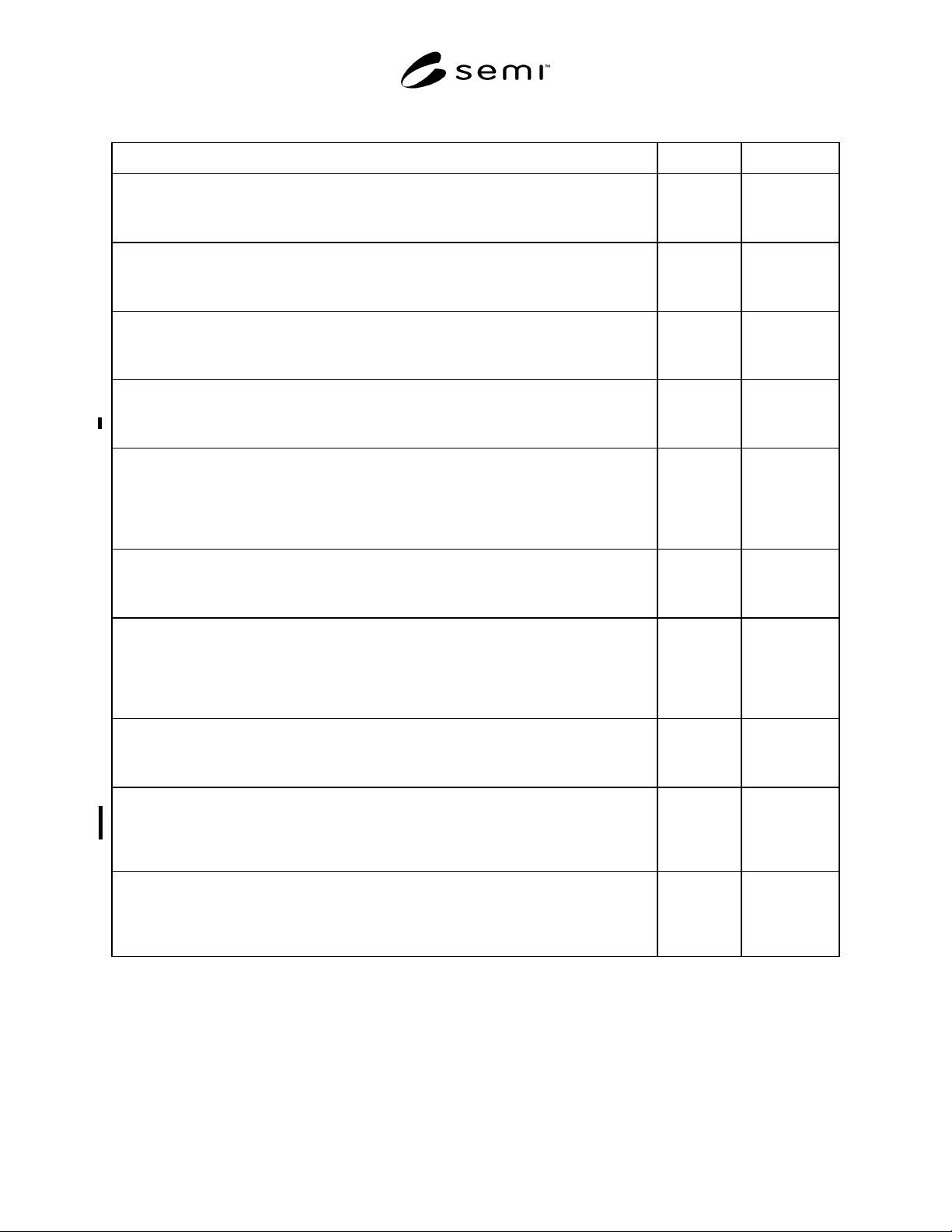
Table 1 Summary of Recommended Specifications
Description Value Units
Internal Surface Chemistry (AUGER)
Surface chromium oxide enhanced layer thickness at
1/2 peak height of measured oxygen signal level
For an example of a test method, see SEMASPEC 90120573B (ESCA)
≥ 15 Å
Internal Surface Chemistry (ESCA)
Total chromium to iron ratio including both reduced
and oxidized stated
For an example of a test method, see SEMASPEC 90120403B (ESCA)
≥ 1.25:1 value
Internal Surface Chemistry (EDX)
Surface foreign elements, those elements not in the
Smelter’s Test Report (SMTR)
Test procedures per ASTM F 1375 (EDX)
0value
Internal Surface Defects
Photos per test method
Counts per photo
Test procedures per ASTM F 1375 (SEM)
5
≤ 50
value
value
Internal Surface Roughness
Average surface roughness
Roughness average (R
a
)
Maximum surface R
a
(individual reading)
For example of a test method, see SEMASPEC 90120400B (Contact Profilometry)
≤ 0.25
(≤ 10)
≤ 0.38
(≤ 15)
µm
(µin.)
µm
(µin.)
Particulate Contribution
at ≥ 0.1 µm size
at ≥ 0.02 µm size
Test procedures per ASTM F 1394 (Particles)
≤ 0.71 (20)
≤ 2.6 (75)
ptc/L (ptc/ft
3
)
ptc/L (ptc/ft
3
)
Internal Absorbed Moisture
Time to recover to base line from a 2 ppm spike
for low surface area component (valve, regulator)
Time to recover to baseline from a 2 ppm spike
for high surface area component (filters, tubing)
Test procedures per ASTM F 1397
≤ 4
≤ 6
hour
hour
Total Anionic Contamination
Total anionic contamination added to test water
Individual anionic contaminant
Test procedures per ASTM D 4327 (Total Anions)
≤ 1
≤ 0.2
ppm
ppm
Leak Rate
Inboard leak rates for He
Outboard leak rate for He
Cross-seat leak rates for He
Test procedures per SEMI F1 (Leak Rate)
≤ 1 × 10
-9
≤ 1 × 10
-5
≤ 1 × 10
-8
scc/s
scc/s
scc/s
Cycle Life
Manual values pressure automatic valves
High Pressure automatic valves
Low Pressure automatic valves
Test procedures per ASTM F 1375 (Cycle Life)
≥ 25 K
≥ 25 K
≥ 500 K
cycles
cycles
cycles