semi合集-English.pdf - 第924页
SEMI E118.1-1104 © SEMI 2003, 2004 1 SEMI E118.1-1104 SPECIFICATION FOR SECS-I AND SECS-II PROTOCOL FOR WAFER ID READER COMMUNICATION INTERFACE STANDARDS This specification was technically approved by the Global Informat…
SEMI E118-1104
E
© SEMI 2002, 2004 17
RELATED INFORMATION 3
APPLICATION NOTES
NOTE: This related information is not an official part of SEMI E118 and was derived from work of the originating
task force. This related information was approved for publication by full letter balot procedures on July 19, 2002.
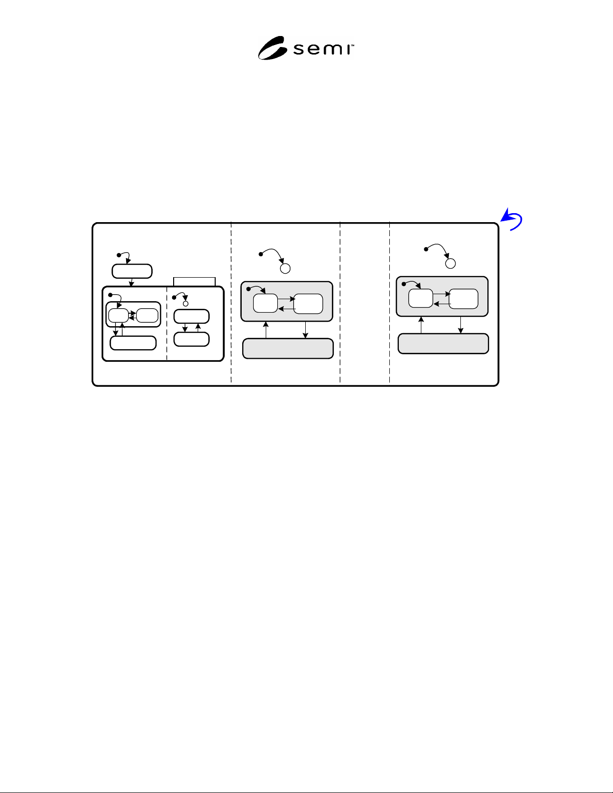
R3-1 Combined State Model
R3-1.1 Figure R3-1 shows the combined state model for the WIDR unit with nn heads, from HEAD01 TO
HEADnn. The WIDR is considered as IDLE when and only when it is in OPERATING and all of its heads are
IDLE.
WIDR
HEAD01
C
12
OPERATING
16
BUSY
IDLE
13
14
15
NOT OPERATING
C
12
HEADnn
11
1
INITIALIZING
3
2
NO
ALARMS
ALARMS
MAINTENANCE
4
5
9
10
ALARM STATUS
OPERATIONAL
RUNNING
IDLE
7
8
6
BUSY
OPERATING
C
OPERATING
16
BUSY
IDLE
13
14
NOT OPERATING
15
.....
Figure R3-1
Combined State Model
NOTICE: SEMI makes no warranties or representations as to the suitability of the standards set forth herein for any
particular application. The determination of the suitability of the standard is solely the responsibility of the user.
Users are cautioned to refer to manufacturer's instructions, product labels, product data sheets, and other relevant
literature, respecting any materials or equipment mentioned herein. These standards are subject to change without
notice.
By publication of this standard, Semiconductor Equipment and Materials International (SEMI) takes no position
respecting the validity of any patent rights or copyrights asserted in connection with any items mentioned in this
standard. Users of this standard are expressly advised that determination of any such patent rights or copyrights, and
the risk of infringement of such rights are entirely their own responsibility.
Copyright by SEMI® (Semiconductor Equipment and Materials
International), 3081 Zanker Road, San Jose, CA 95134. Reproduction of
the contents in whole or in part is forbidden without express written
consent of SEMI.
SEMI E118.1-1104 © SEMI 2003, 2004 1
SEMI E118.1-1104
SPECIFICATION FOR SECS-I AND SECS-II PROTOCOL FOR WAFER
ID READER COMMUNICATION INTERFACE STANDARDS
This specification was technically approved by the Global Information and Control Committee and is the
direct responsibility of the Japanese Information and Control Committee. Current edition approved by the
Japanese Regional Standards Committee on July 23, 2004. Initially available at www.semi.org September
2004; to be published November 2004. Originally published March 2003; last published March 2004.
1 Purpose
1.1 This document maps the services and data of the
Wafer ID Reader (WIDR) standard to SECS-II streams
and functions and data definitions.
2 Scope
2.1 This document applies to all implementations of
WIDR that use the SECS-II message protocol (SEMI
E5).
NOTICE: This standard does not purport to address
safety issues, if any, associated with its use. It is the
responsibility of the users of this standard to establish
appropriate safety and health practices and determine
the applicability of regulatory or other limitations prior
to use.
3 Referenced Standards
3.1 SEMI Standards
SEMI E4 — SEMI Equipment Communications
Standard 1 Message Transfer (SECS-I)
SEMI E5 — SEMI Equipment Communications
Standard 2 Message Content (SECS-II)
NOTICE: Unless otherwise indicated, all documents
cited shall be the latest published versions.
4 Terminology
4.1 Abbreviations and Acronyms
4.1.1 SECS — SEMI Equipment Communications
Standard
4.1.2 WIDR — Wafer ID Reader
5 Physical Requirements
5.1 The WIDR using the SECS-I protocol shall use a
9-pin female connector.
6 Service Message Mapping
6.1 Table 1 shows the specific SECS-II streams and
functions that shall be used for SECS-II
implementations of the service messages defined in
SEMI E118
.
6.2 Request and notification messages are mapped to
primary (odd-numbered) SECS-II functions and
response messages are mapped to secondary (even-
numbered) SECS-II functions.
6.3 In some cases, a common set of parameters allows
more than one service to be mapped to the same stream
and function, with an additional SECS-II data item used
to differentiate between the two services.
Table 1 Services Mapped to SECS-II Messages
Message Name Stream,Function SECS-II Name
ChangeState S18,F13/F14 Subsystem Command Request/Acknowlege
Get Attributes S18,F1/F2 Read Attribute Request/Data
Get Status S18,F13/F14 Subsystem Command Request/Acknowledge
Perform Diagnostics S18,F13/F14 Subsystem Command Request/Acknowledge
Read WID S18,F9/F10 Read ID Request/Data
Reset S18,F13/F14 Subsystem Command Request/Acknowledge
Set Attributes S18,F3/F4 Write Attribute Request/Acknowledge
Read WIDC S18,F15/F16 Read 2D Code Condition Request/Data
SEMI E118.1-1104 © SEMI 2003, 2004 2
7 Service Parameter to Data Item Mapping
7.1 Table 2 shows the mapping between message parameters defined by WIDR and data items defined by SECS-II.
For parameters specified in the definitions of a WIDR service, either the parameters themselves, or individual
elements of complex parameters, map to a specific data item.
Table 2 Service Parameters to Data Item Mapping
Parameter Name SECS-II Data Item Format Values
Attribute ID ATTRID 20 Name of attribute
Attribute Value ATTRVAL 20
HeadID TARGETID 20 “00”-“31”
Identifies either an individual head (“01”-
“31”) or the WIDR subsystem itself (“00”).
PM Information STATUS 20 “NE” = Normal execution, “MR” =
Maintenance required
Result Status SSACK 20 “NO” = Normal operation;
“EE” = Execution error;
“CE” = Communication error;
“HE” = Hardware error
StateRequest CPVAL 20 “OP”, “MT”
Status STATUSLIST L,4
1. <PMInformation>
2. <AlarmStatus>
3. <OperationalStatus>
4. <HeadStatus>
Current values of PM Information with the
corresponding attributes for WIDR and Head
(if applicable). See Tables 4 and 5.
Wafer ID MID 20
2D Code Read Condition CONDITIONLIST L,7
1. <Cell Size>
2. <Contrast>
3. <Damage Percent>
4. <Number Error Bits>
5. <Read Time>
6. <Matrix Style>
7. <Matrix Polarity>
Current values of Cell Size, Contrast,
Damage Percent, Number Error Bits, Read
Time, Matrix Style, Matrix Polarity with the
corresponding attributes for Code Condition.
See Table 6.
CONDITIONLIST data shall be formatted in
the fixed order as in Format column.
NOTE 1: There are also data items used in SECS-II messages that do not map to specific services parameters. Services with the same set of
parameters are mapped to the same SECS-II message by adding an additional data item to differentiate between the services. Table 3 contains the
SECS-II data items that have not a corresponding WIDR service parameter.
Table 3 Additional Data Requirements Table
SECS-II Data Item Function Value
SSCMD Used to differentiate between different subsystem commands
indicated.
“ChangeState”
“GetStatus”
“Perform Diagnostics”
“Reset”