semi合集-English.pdf - 第823页
SEMI E112-0305 © SEMI 2001, 2005 5 6.15 Inf o Pads — When the MRSP is placed on a port, the info pads A, B, C, and D communicate inform ation about the RSP configuration . Figure 10 shows the dimensions o f the info pa d…
SEMI E112-0305 © SEMI 2001, 2005 4
Figures 4 and 6. No obstructions should exist in the reticle lift clearance exclusion volumes which extend in the y
direction (normal to the facial reference plane).
6.7.4 Safety Rail Exclusion Volumes — Volumes in an opened pod which must remain free from intrusion to
accommodate safety rails which may be used on end-effectors to protect the edge of the reticle during handling. No
obstructions should exist in the safety rail exclusion volumes which extend in the y direction (normal to the facial
reference plane) as defined by x241 and z301 in Table 2 and shown in Figure 4.
6.7.5 Rear Retainer Volume — Volume in an opened pod in which any reticle rear retainer must exist. The volume
is defined by x242 and y226 as shown in Figure 7 and Table 2.
NOTE 1: This volume is never to be accessed by an end-effector.
6.7.6 Reticle Backstops — The interior of the MRSP150 shall have reticle backstops which may be used by end-
effectors to position the reticle when being removed from the MRSP150.
NOTE 2: These are the minimum required backstops, the backstops may be larger than this minimum specification, occupying
any part of the rear retainer volume. The dimensions are defined by x249, x250, y239 and z314 as shown in Table 2 and in
Figure 7.
6.7.7 RFID Placement Zone — Zone in the pod where the RFID transponder is placed, which may be used for RF
communications during reticle handling. The entire RFID transponder must be positioned within the zone defined by
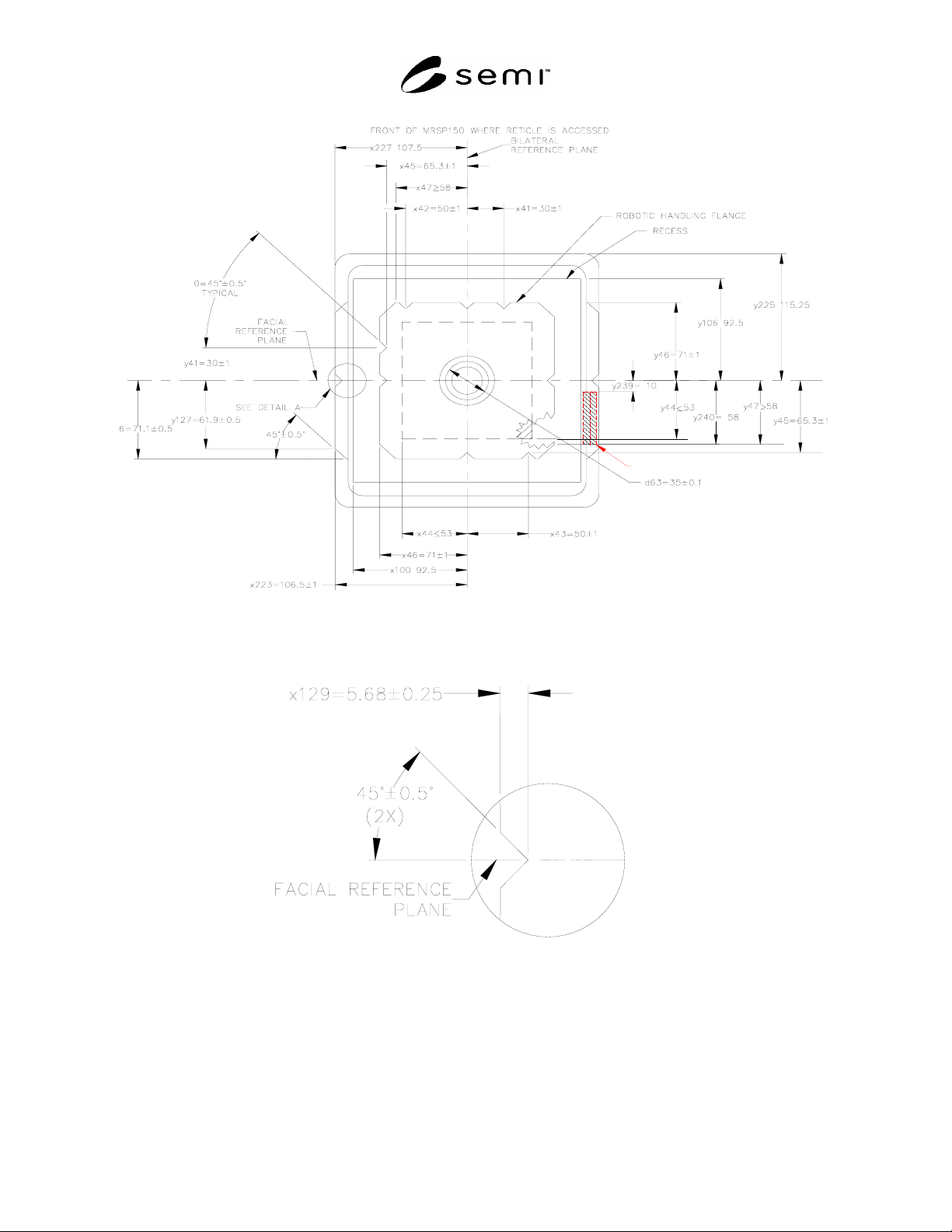
x251, x252, y239, y240, z308, z315, z316 in Table 2 and shown in Figures 1, 3, 11. Pod suppliers may also place
other features in this placement zone (such as the pod wall, RFID transponder support brackets, etc).
6.8 External Dimensions — Figures 1, 2, 3, 5 and 10 show, respectively, the external top view, a detail, the rear
view, the robotic handling flange and the conveyor rails of the MRSP150. Table 2 defines the external dimensions
of the MRSP150.
6.9 Internal Dimensions — Figures 4, 6 and 7 show internal dimensions of the MRSP150. Table 2 defines the
internal dimensions of the MRSP150.
6.10 Robotic Handling Flange — On the top of the pod is an optional robotic handling flange for automated
manipulation of the MRSP150. Figures 1, 3 and 5 show dimensions for the robotic handling flange. Table 2 defines
the dimensions for the robotic handling flange.
6.11 Recess — Surface on the top of the pod defined by dimensions x100, y106 and z281. Figures 1 and 3 show
dimension for the recess. The recess provides clearance for use of robotic handling flange.
NOTE 3: The raised surface around the recess is not required.
6.12 Side Handling Flanges — On the sides of the pod parallel to the bilateral reference plane are optional handling
flanges for automated manipulation of the MRSP150. Figures 1, 2 and 3 show dimensions for the side handling
flanges. Table 2 defines the dimensions for the side handling flanges. No obstructions may exist in the side handling
exclusion volumes which extend in the y direction (normal to the facial reference plane) as defined by x236 and
z286.
6.13 Conveyor Rails — Surfaces on the bottom of the MRSP150 used to transport the MRSP on conveyors. The
rails consist of smooth portions of the bottom periphery, parallel with each other, on two opposite sides, and
extending at least y236 from the facial reference plane (optionally the full length) on those sides. Surfaces on these
portions of the bottom periphery should be uninterrupted (ie. no notches in the surface along the bottom or the side).
No other feature of the carrier may extend below the plane defined by the surfaces of the conveyor rails. The
conveyor rail surfaces are bounded by x247, x248 and y236 as shown in Figure 10. Table 2 defines the dimensions
for the conveyor rails.
6.14 Inner and Outer Radii — All required concave features may have a radius of up to r65 to allow cleaning and
to prevent contaminant build-up. All required convex features may also have a radius of up to r66 to prevent small
contact patches with large stresses that might cause wear and particles.
NOTE 4: These limits on the radius of all required features are specified as a maximum (not a minimum) to ensure that the
required features are not rounded off too much. The lower bound on the radius is up to the carrier supplier.
NOTE 5: This radius applies to every required feature unless another radius is called out specifically. Here a required feature is
an area on the surface of the carrier specified by a dimension (or intersections of dimensions) that has a tolerance and not just a
maximum or minimum (such as the edges of the robotic handling flange).
SEMI E112-0305 © SEMI 2001, 2005 5
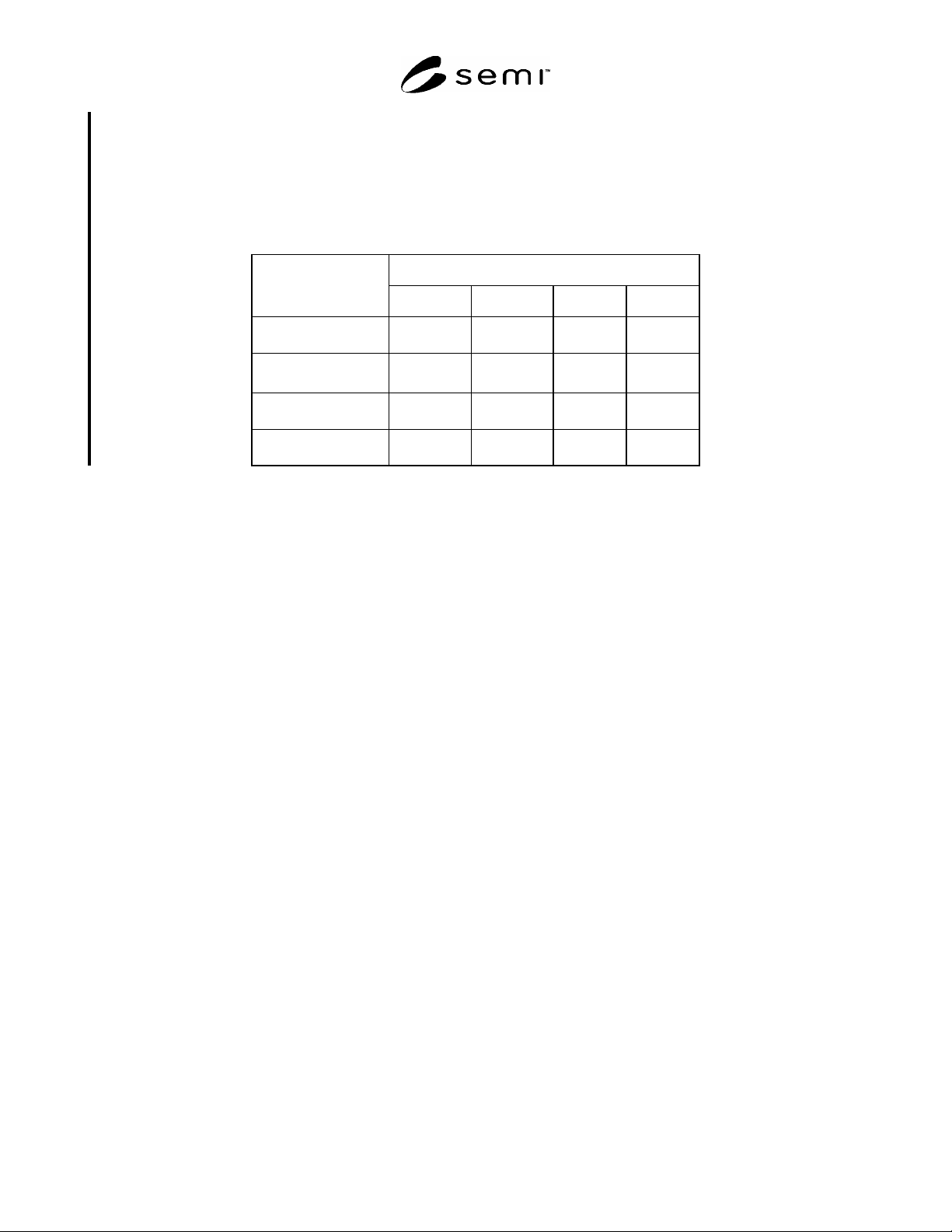
6.15 Info Pads — When the MRSP is placed on a port, the info pads A, B, C, and D communicate information
about the RSP configuration. Figure 10 shows the dimensions of the info pads. Table 2 defines the info pad
dimensions. A pad in the up position must be z26 above the horizontal reference plane. A pad in the down position
must be z2 above the horizontal reference plane. Info pad assignments are shown in Table 1. Info pads that are “not
defined” can be at either the up or down position unless specified by the end user. RSP configurations “to be
assigned” may be assigned by the end user.
Table 1
Info Pad
MRSP Configuration
A B C D
6 inch reticle not
defined
not
defined
up down
to be assigned not
defined
not
defined
down down
to be assigned not
defined
not
defined
up up
to be assigned not
defined
not
defined
down up
7 Related Documents
7.1 SEMI Standards
SEMI P1 — Specification for Hard Surface Photomask Substrates
SEMI S8 — Safety Guidelines for Ergonomics Engineering of Semiconductor Manufacturing Equipment
NOTICE: Unless otherwise indicated, all documents cited shall be the latest published versions.
SEMI E112-0305 © SEMI 2001, 2005 6
RFID PLACEMENT ZONE
Figure 1
External Top View of MRSP150
Figure 2
Detail A: External Top View of Side Handling Flange Alignment Notch