semi合集-English.pdf - 第199页
SEMI E25-92 © SEMI 1992, 2004 2 4.3 Outboar d Plane — The outboard surface shoul d be limited to non-rigid lines. To minimize potential mechanical damage, chemical utilities sh ould not enter through the lower half of th…

SEMI E25-92 © SEMI 1992, 2004 1
SEMI E25-92 (Withdrawn 1104)
CLUSTER TOOL MODULE INTERFACE: MODULE ACCESS
GUIDELINE
This guideline was technically approved by the Global Physical Interfaces & Carriers Committee and is the
direct responsibility of the North American Physical Interfaces & Carriers Committee. Current edition
reapproved by the North American Regional Standards Committee on August 16, 2004. Initially available at
www.semi.org September 2004; to be published November 2004. Originally published in 1992; last
published June 1999.
Minor editorial changes were made to this document to conform to editorial guidelines.
NOTICE: This document was balloted and approved
for withdrawal in 2004.
1 Introduction
1.1 Scope — This guideline specifies an envelope
within which a cluster tool module is situated. Entry
and exit locations through the envelope and connection
locations to the module for utilities and facility services
are recommended.
1.2 Purpose — The purpose of the cluster tool module
access guideline is to provide assistance in the place-
ment of utilities and facility services to cluster tool
modules in order to improve access for maintenance
and service and to simplify cluster tool installation.
1.3 Impact — This guideline recommends that equip-
ment designs limit the placement of utility lines and
facility services to specific portions of the module
envelope.
1.4 Exceptions — Local safety regulations must always
take precedence over this guideline. Local conditions
may justify exceptions to this guideline.
NOTICE: This standard does not purport to address
safety issues, if any, associated with its use. It is the
responsibility of the user of this standard to establish
appropriate safety and health practices and determine
the applicability of regulatory or other limitations prior
to use.
2 Referenced Documents
2.1 SEMI Documents
SEMI E20 — Cluster Tool Module Interface: Electrical
Power and Emergency Off Standard
SEMI E21 — Cluster Tool Module Interface:
Mechanical Interface and Wafer Transport Standard
SEMI E24 — Cluster Tool Module Interface: Isolation
Valve Interlocks Standard
SEMI S2 — Safety Guidelines for Semiconductor
Manufacturing Equipment
NOTICE: Unless otherwise indicated, all documents
cited shall be the latest published versions.
3 Module Envelope
3.1 For the purpose of this guideline, the module enve-
lope is taken to be a set of six surfaces that completely
encloses a module. Individual module envelopes may
contact but not penetrate adjacent module envelopes.
The six surfaces are the inboard and outboard planes,
the two sides, the bottom and the top.
3.2 The inboard plane is the interface plane between a
transport module and any other module as defined in
SEMI E21; thus, a transport module possesses multiple
inboard planes. The outboard surface is parallel to the
interface plane and normally coincides with that part of
the module which is farthest from the interface plane.
Each side of the module envelope consists of several
vertical planes. The bottom surface generally coincides
with the floor, and the top is a horizontal plane that con-
tains the highest point of the module.
3.3 In the sections that follow, the distinction between
the physical module and the space reserved for the
module within the envelope must be kept in mind. Sec-
tion 4 refers to where utility lines penetrate the enve-
lope, and Section 5 refers to constraints on where these
lines connect to the physical module.
4 Allocation of Module Envelope Surfaces
4.1 The allocation of surfaces is subject to the need for
access to the interface plane, module movement, main-
tenance access space, and protection of module compo-
nents (particularly electrical components) from liquid
leaks.
4.2 Inboard Plane — To allow access to the isolation
valve(s), no utilities or facility services should be rout-
ed through the inboard surface close to the valve
boundary. ( See SEMI E21) The inboard surface is pre-
ferred for intra-tool communications, EMO (see SEMI
E20) and the interlock interface between the transport
module and the attached modules. (See SEMI E24.)

SEMI E25-92 © SEMI 1992, 2004 2
4.3 Outboard Plane — The outboard surface should be
limited to non-rigid lines. To minimize potential
mechanical damage, chemical utilities should not enter
through the lower half of this surface.
4.4 Sides — In order to facilitate maintenance access,
utilities and facility services should not penetrate the
module envelope sides.
4.5 Top Surface — The top surface is preferred for
power, exhaust, process gases and make-up air.
Communications and electronic control harnesses could
also enter through this surface.
4.6 Bottom Surface — The bottom surface is preferred
for vacuum lines and all liquid supplies, returns and
drains. The location of all lines should not restrict the
removal of the module.
5 Module Considerations
5.1 The locations of utility and facility lines and
connections to the module, which is located within the
module envelope, are given below.
5.2 Exhaust, Vacuum and Make-up Air — The size of
piping for exhaust, vacuum and make-up air suggests
that the module sides are undesirable locations for
connections.
5.3 Maintenance Access — Utility and facility lines
and connections to the module sides should not com-
promise maintenance access to the module. Connect-
ions should be located above or below areas requiring
periodic maintenance access.
5.4 Liquids — Liquid supply connections to the
module sides should be as low as practical.
5.5 Electrical Components — Electrical components
that need to be accessible for maintenance while
energized should not be located at the sides of the
module. (See SEMI S2.)
5.6 Remote Equipment — For ease of maintenance
access, some pieces of equipment (for example, coolant
chiller and RF power supplies) may be located outside
the module envelope. In such cases, the lines and
connections between the remote equipment and the
module should follow this guideline.
6 Examples
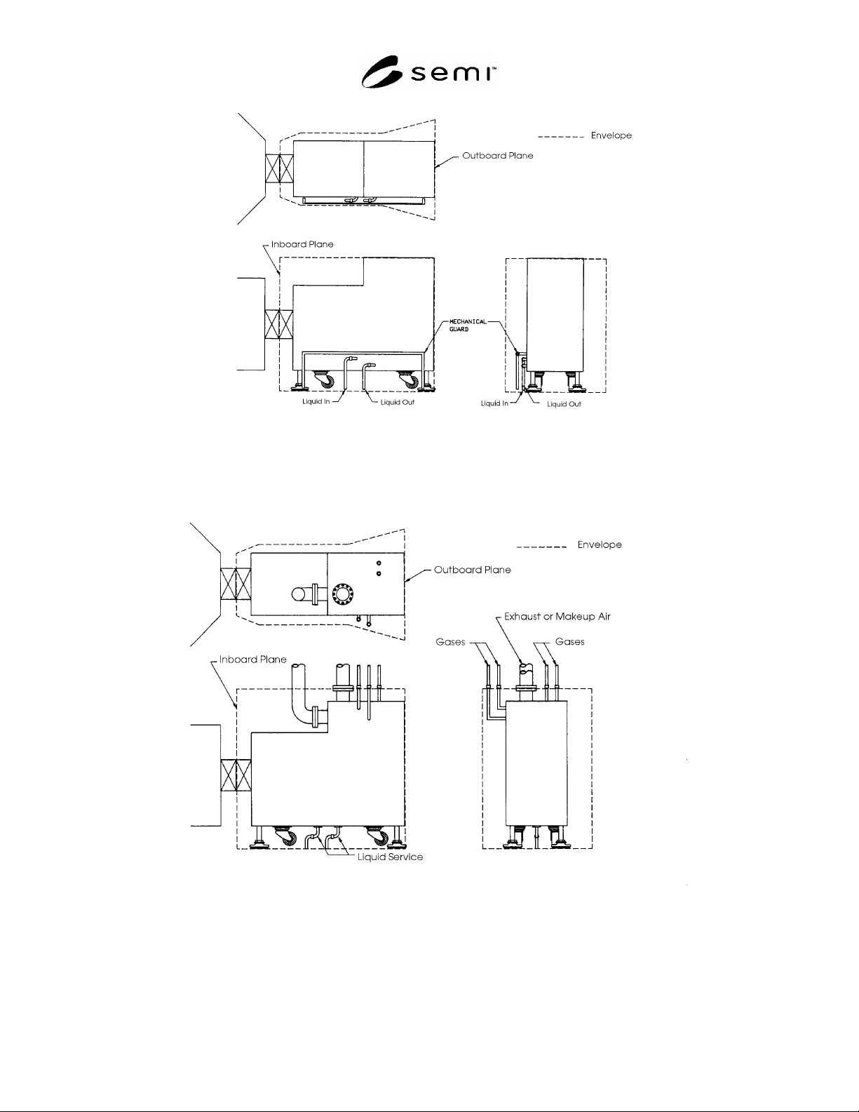
6.1 The relationship between the location of specific
utility and facility lines entering the module envelope
and their subsequent routing and connection to the
module within the module envelope is illustrated by the
following examples.
6.2 Liquid Connections — Two suggested methods of
providing liquid connections are shown in Figures 1
and 2. The liquid lines enter through the bottom of the
module envelope (see Section 4.5) then connect to
either the side of the module or the bottom of the
module (see Section 5.3).
6.3 Gas Connections — Two suggested methods of
providing gas connections are shown in Figure 2. The
gas lines pass through the top of the module envelope
(see Section 4.4), and then connect to the module either
at the top or at the side.
6.4 Exhaust and/or Make-Up Air — Two suggested
methods of providing exhaust and/or make-up air
connections are shown in Figure 2. The exhaust line
passes through the top of the module envelope (see
Section 4.4) and then connects to the module at or near
the top. Exhaust and make-up air connections are
flanged in Figure 2.
SEMI E25-92 © SEMI 1992, 2004 3
Figure 1
Figure 2
7 Related Documents
7.1 SEMI Documents
SEMI E6 — SEMI Facilities Interface Specifications
Guideline and Format