semi合集-English.pdf - 第3995页
SEMI F45-0699 © SEMI 1999 3 Figure 5B Marking Applicat ion Example 7 Outside Diam eter T oleran c e 7.1 T he Outside Diameter toleranc e of 6.35 mm (1/4 in.), 9.53 m m (3/8 in.) and 12.7 mm (1/2 in.) is + 0.1 mm, - 0.0 m…
SEMI F45-0699 © SEMI 1999 2
Figure 3B
Dimensions of Reducing Elbow Weld Fittings
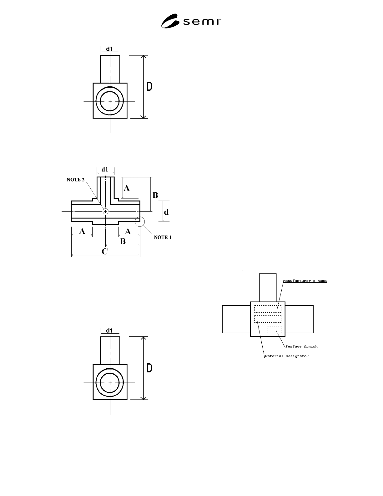
Figure 4A
Dimensions of Reducing Tee Weld Fittings
NOTE 1: Machined tube weld ends shall be square tolerance ±
0.5°.
NOTE 2: Intersection shall be square tolerance ± 0.5°.
Figure 4B
Dimensions of Reducing Tee Weld Fittings
6 Marking the Reducing Weld Fittings
6.1 Marks include 1), 2), 3), 4), 5), 6) and 7). Marks
1) through 4) shall be made on the reducing weld
fittings body. Marks 5) - 7) shall be made on the
reducing weld fittings body or its package (both
individual bagging and box).
1) Manufacturer's name
2) Material designator
3) Surface finish designator
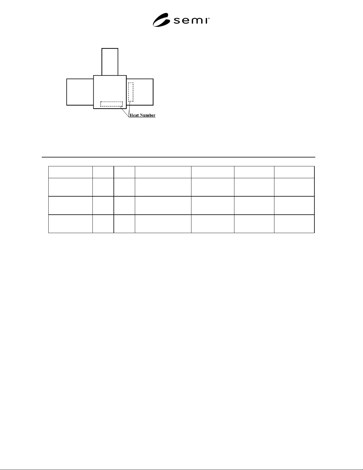
4) Heat Number
5) Lot Number (optional)
6) Model (Part Number)
7) Wall thickness of tube end
6.2 To be agreed upon between supplier and user for
marking items and marking locations. The example
below explains marking applications. (see Figures 5A
and 5B)
6.3 Manufacturer's name, Material designator, Surface
finish designator and Heat Number should be marked
on the body. The Heat Number shall be marked either
on the body of the cube along with the other
information, but if space is limited, then the Heat
Number marked on the tube Outside Diameter close to
the body is permissible.
Figure 5A
Marking Application Example
SEMI F45-0699 © SEMI 19993
Figure 5B
Marking Application Example
7 Outside Diameter Toleran ce
7.1 The Outside Diameter tolerance of 6.35 mm (1/4
in.), 9.53 mm (3/8 in.) and 12.7 mm (1/2 in.) is + 0.1
mm, - 0.0 mm (+ 0.004 in., - 0.000 in.).
8 Wall Thickness of Tube E nd
8.1 Wall thickness of tube end should be either 1 mm
(0.039 inch) or 0.89 mm (0.035 inch), 1.24 mm (0.049
inch) and the thickness should be marked on the
reducing weld fitting body or its package. Wall
thickness tolerance is ± 8%.
Table 1 Dimensions and Tolerance
Nominal Diameter d d1 A B C D
9.53 × 6.35
(3/8 × 1/4)
9.53
(0.375)
6.35
(0.25)
6.35 + 0.1/ - 0.05
(0.25 + 0.004/ - 0.002)
11.9 ± 0.1
(0.4685 ± 0.004)
23.8 ± 0.1
(0.937 ± 0.004)
17.45 ± 0.1
(0.687 ± 0.004)
12.7 × 6.35
(1/2 × 1/4)
12.7
(0.5)
6.35
(0.25)
6.35 + 0.1/ - 0.05
(0.25 + 0.004/ - 0.002)
13.5 ± 0.1
(0.5315 ± 0.004)
27.0 ± 0.1
(1.063 ± 0.004)
20.65 ± 0.1
(0.813 ± 0.004)
12.7 × 9.53
(1/2 × 3/8)
12.7
(0.5)
9.53
(0.375)
6.35 + 0.1/ - 0.05
(0.25 + 0.004/ - 0.002)
13.5 ± 0.1
(0.5315 ± 0.004)
27.0 ± 0.1
(1.063 ± 0.004)
20.65 ± 0.1
(0.813 ± 0.004)
Dimensions: mm (in.)
NOTICE: These standards do not purport to address
safety issues, if any, associated with their use. It is the
responsibility of the user of these standards to establish
appropriate safety and health practices and determine
the applicability of regulatory limitations prior to use.
SEMI makes no warranties or representations as to the
suitability of the standards set forth herein for any
particular application. The determination of the
suitability of the standard is solely the responsibility of
the user. Users are cautioned to refer to manufacturer's
instructions, product labels, product data sheets, and
other relevant literature respecting any materials
mentioned herein. These standards are subject to
change without notice.
The user's attention is called to the possibility that com-
pliance with this standard may require use of copy-
righted material or of an invention covered by patent
rights. By publication of this standard, SEMI takes no
position respecting the validity of any patent rights or
copyrights asserted in connection with any item men-
tioned in this standard. Users of this standard are ex-
pressly advised that determination of any such patent
rights or copyrights, and the risk of infringement of
such rights are entirely their own responsibility.
Copyright by SEMI® (Semiconductor Equipment and Materials
International), 3081 Zanker Road, San Jose, CA 95134. Reproduction o
f
the contents in whole or in part is forbidden without express written
consent of SEMI.

SEMI F46-0999 © SEMI 19991
SEMI F46-0999
GUIDE FOR ON-SITE CHEMICAL GENERATION (OSCG) SYSTEMS
This guide was technically approved by the Global Facilities Committee and is the direct responsibility of the
North American Facilities Committee. Current edition approved by the North American Regional Standards
Committee on April 15, 1999. Initially available on www.semi.org August 1999; to be published September
1999.
1 Purpose
1.1 This guide establishes the minimum System and
Overall Implementation requirements for requirement
of On-Site Chemical Generation (OSCG) used in
semiconductor manufacturing. It is also intended to
establish a common basis for developing detailed
guides in subsequent documents concerning design,
performance, and certification of OSCG systems.
2 Scope
2.1 This guide applies to the OSCG system design
used for the generation of chemicals, particularly ultra
high purity, used in the silicon wafer, integrated circuit,
and/or substrate manufacturing processes. These will
include, but are not limited to, various concentrations of
NH
4
OH, HCl, HF, and NH
4
F aqueous solutions.
2.2 This standard does not purport to address all of the
safety issues associated with its use. It is the
responsibility of the users of this standard to establish
appropriate safety and health practices and determine
the applicablity of regulatory limitations prior to use.
3 Limitations
3.1 This guide is not intended to cover all chemicals
used in these processes but only to those that can be
generated, on-site, by means of reacting ultra-pure
process gas with the appropriate liquid solution.
3.2 This guide is not intended to be applicable to
“Point-of Use” generated process solutions.
3.3 This guide excludes construction protocols for
OSCG such as clean manufacturing, integrity of
fabrication, and prequalification of materials.
3.4 This guide does not intend to cover all the
important safety considerations which relate to the
OSCG systems, feed gas, equipment, or installations.
4 Referenced Standards
4.1 SEMI Standard
SEMI S2 Safety Guidelines for Semiconductor
Manufacturing Equipment
NOTE: As listed or revised, all documents cited shall be the
latest publications of adopted standards.
5 Terminology
blending (or dilution) the combination of two or
more chemicals (one of which may be DI water) to
create the desired solution mixture.
clean sampling a specifically designed scheme to
allow for the taking of chemical samples, avoiding any
contamination from the operator or background
environment of the area.
day tank a chemical storage vessel, of appropriate
material(s), used to store a volume of product chemical
that could be consumed in one or more days.
DI water high purity 18 megohm water
OSCG system the stand-alone unit that produces (or
uses) a high purity gas and reacts it with water (or the
appropriate aqueous solution) to produce the desired
ultra pure chemical solution. This unit is intended for
use on the manufacturing site and in a centralized
scheme to support all or a portion of the site’s chemical
requirement(s).
overall implementation this term is used to refer to
the entire scope for an OSCG installation, including the
Gas Storage/Supply system, the OSCG system,
chemical storage tanks, chemical plumbing, and
interface with the chemical distribution system. Gas
supplies are covered in related guides.
process plumbing tubing or piping whose surface is
directly in contact with the chemical. Typically
constructed from high purity perfluorinated materials or
other high purity polymers.
product chemical the name given to the actual
chemical produced on site by the OSCG system.
pump a mechanical or pneumatically operated
device used to create hydraulic force for chemical
transfer.
QC tank storage tank for the staging of chemical to
be quality verified prior to release to the Product
storage tank. This optional quality verification scheme
allows for 100% chemical verification.
secondary containment pipe or tubing that contains
the process plumbing intended to provide a second level
of containment in the event of failure of the primary