semi合集-English.pdf - 第6561页
SEMI G84-0303 © SEMI 2001, 2003 11 11.5 In Process Strip Ma p Related Errors 11.5.1 Each equipment ty pe shall defi ne the type of errors that can occ ur during processi ng which could cause strip map integrity prob lems…
SEMI G84-0303 © SEMI 2001, 2003 10
11.3.1.1 An Event Report “Update Map” will be sent if
new defects have been detected and not previously
logged to the host for the following conditions. See
Figure 3.
1. At the end of processing current strip if new
defects have been detected
2. Whenever the equipment changes state from
Remote to Local
3. Whenever the equipment interlocks are triggered
4. Whenever the equipment stops and requires
operator intervention.
11.3.2 Unsuccessful Transaction
11.3.2.1 Equipment will stop and signal an alarm to the
host if the equipment detects that a strip map has not
been successfully uploaded to the host.
11.3.2.2 When possible, the equipment shall support
intervention by the Operator with the following
corrective actions:
1. “retry upload”
2. “abort upload”
11.3.2.3 If the “retry upload” is selected the Upload
Event will be resent to the host.
11.3.2.4 If “abort” is selected by the operator an
appropriate Event shall be sent with the strip map ID to
indicate to the host that the strip map has been aborted.
The equipment will not process the strip unless the
equipment is removed from “strip map” mode.
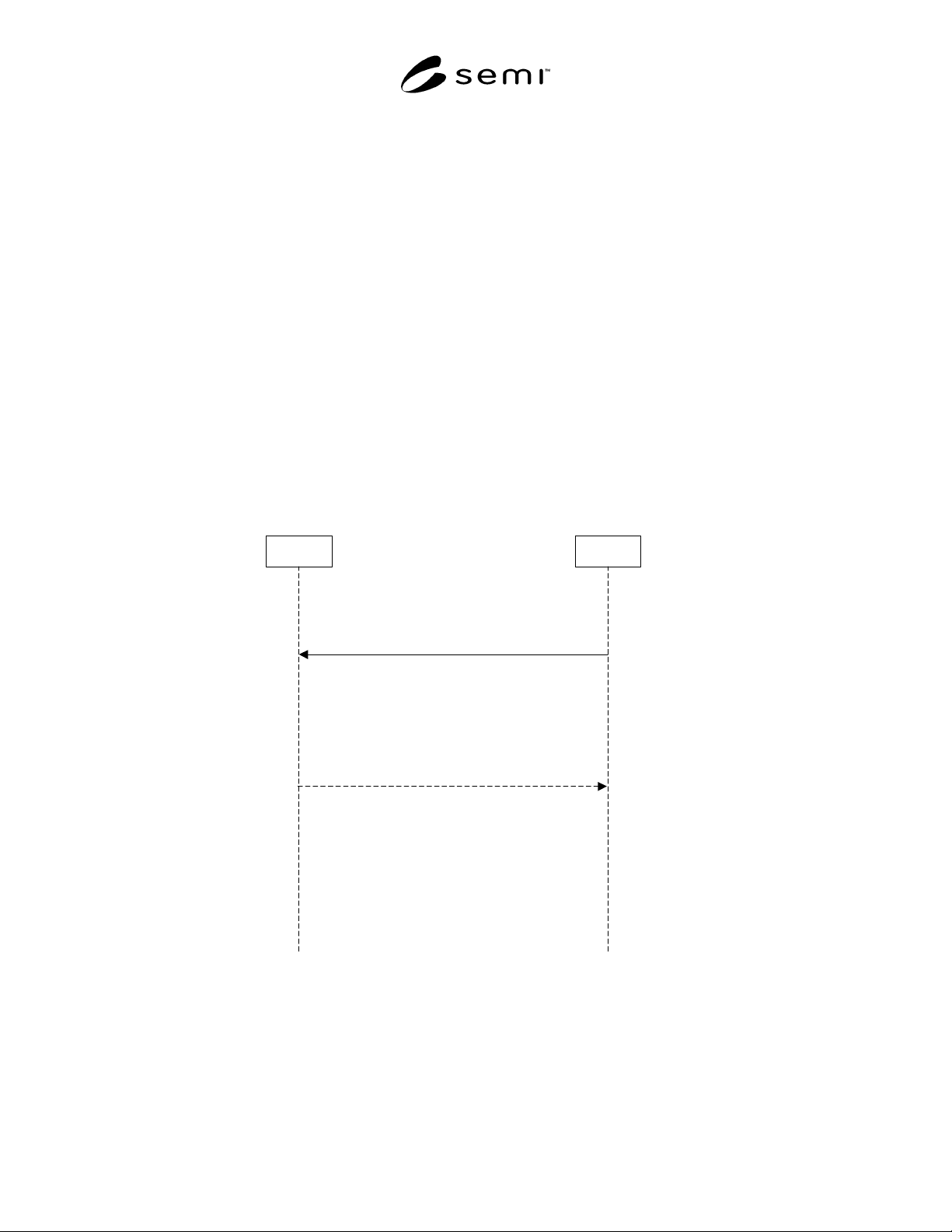
11.4 Strip End Event
11.4.1 At the end of each strip, a strip end event shall
be sent to the host which indicates that the strip has
successfully completed the activity at that equipment.
Event Report Acknowledge
S6,F12
Strip End Event is
received and validated
Equipment completes processing
of the active strip. The strip map
has been successfiully uploaded
to the host - if defects were
detected.
Event Report Send "Strip End"
S6,F11
Equipment
Equipment/Operator
Actions which should be
performed
Host Actions which
should be performed
Host
Figure 4
“Strip End” Event

SEMI G84-0303 © SEMI 2001, 2003 11
11.5 In Process Strip Map Related Errors
11.5.1 Each equipment type shall define the type of
errors that can occur during processing which could
cause strip map integrity problems and provide
documented scenarios of how the equipment will
handle each situation.
11.5.2 Some potential erroneous situations:
• Equipment lost strip map while processing
• Strip is removed prior to completing processing
strip
• Strip jams before being moved out of equipment—
no Strip Map End Event occurred
SEMI G84-0303 © SEMI 2001, 2003 12
APPENDIX 1
STRIP MAP
NOTICE: The material in this appendix is an official part of SEMI G84 and was approved by full letter ballot procedures on
August 27, 2001.
A1-1 This appendix shows how the map data items may be applied to strips as well as some additional information
specific to this substrate type.
A1-2 The StripID shall follow the SEMI T9 specification, when applicable, or may be user definable by the factory.
A1-3 For any given process there must be a way to ensure correct orientation of the strip. The end user is
responsible for providing a master manufacturing drawing showing the top side of the strip. This drawing must show
any special markings or patterns that are needed to reliably flip and rotate a physical strip until it is oriented the
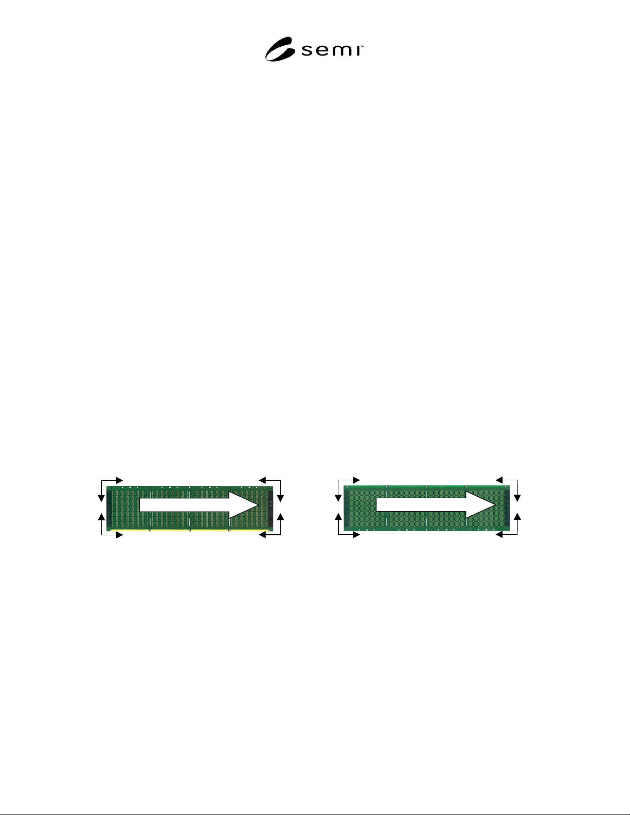
same as the drawing. Figure A1-1 defines what is meant by top side and hence bottom side. It also defines what is
meant by upper, lower and left and right.
A1-4 Each strip type will have a factory defined value for OriginLocation. This is the origin reference for the row 1,
column 1 location on the strip. The factory origin, OriginLocation is selected as one of four corners by the factory
host system. The row and column index will be referenced from the selected reference. This information will be
provided to the equipment by the host in each strip map download scenario.
1 = Upper right (UR) top side
2 = Upper left (UL) top side
3 = Lower left (LL) top side
4 = Lower right (LR) top side
6 = Upper right (UR) bottom side
7 = Upper left (UL) bottom side
8 = Lower left (LL) bottom side
9 = Lower right (LR) bottom side
Row Row
Column
Row Row
Column Column
Column
Std Process Direction
12
34
Top Side
Row Row
Column
Row Row
Column Column
Column
Std Process Direction
67
89
Bottom Side
Figure A1-1
Factory Origin Settings
NOTICE: SEMI makes no warranties or representations as to the suitability of the standard set forth herein for any
particular application. The determination of the suitability of the standard is solely the responsibility of the user.
Users are cautioned to refer to manufacturer’s instructions, product labels, product data sheets, and other relevant
literature respecting any materials mentioned herein. These standards are subject to change without notice.
The user’s attention is called to the possibility that compliance with this standard may require use of copyrighted
material or of an invention covered by patent rights. By publication of this standard, SEMI takes no position
respecting the validity of any patent rights or copyrights asserted in connection with any item mentioned in this
standard. Users of this standard are expressly advised that determination of any such patent rights or copyrights, and
the risk of infringement of such rights, are entirely their own responsibility.
Copyright by SEMI® (Semiconductor Equipment and Materials
International), 3081 Zanker Road, San Jose, CA 95134. Reproduction o
f
the contents in whole or in part is forbidden without express written
consent of SEMI.