semi合集-English.pdf - 第6969页
SEMI S9-1101 © SE MI 1995, 2001 6 Table 1 Maximum T emperature Li mit Parts of the Equipment Temperature Limit (°C) Knife switch blad e and contact j aws 55 Fuse and fuse clip 110 Rubber a nd therm oplastic ins ulated co…

SEMI S9-1101 © SEMI 1995, 20015
9.9 Safety Circuit Function Test
9.9.1 Test Equipment Depends on safety devices
being tested.
9.9.2 Procedure — Functionally test each safety circuit
(e.g., EMO, Emergency Stop, End-of-travel sensors,
loss of exhaust sensors, light curtains, and safety
interlocks) by actuation and resetting.
9.9.3 Acceptable Results The following sections
provide the acceptable results for the applicable safety
systems.
9.9.3.1 When the EMO is actuated, all hazardous
voltage and all power greater than 240 volt-amps in the
equipment beyond the main power enclosure should be
de-energized, except where permitted by SEMI S2.
9.9.3.2 Actuation of the emergency stop and safety
interlocks causes the equipment, or relevant parts of the
equipment, to be automatically brought to a safe
condition.
9.9.3.3 Resetting of the safety circuit should not cause
the system to resume operation.
NOTE 12: This test documents the electrical functionality of
the safety circuit(s). It is not intended to determine or
document the appropriateness of the shutdown actions taken.
9.10 Safety Circuit Conductor Disconnection Test
9.10.1 Test Equipment None.
9.10.2 Procedure — For each independent safety
interlock (such as door interlock), EMO, and safety
sensor (e.g., exhaust sensor, low fluid level sensor),
disconnect each conductor, in turn, and each connector,
in turn.
9.10.3 Acceptable Results The following sections
provide the acceptable results for the applicable safety
circuits.
9.10.3.1 The opening of the safety circuit causes the
equipment to be placed in a safe condition as if the
safety device had been actuated
9.10.3.2 Reconnecting the conductor should not cause
the system to resume operation.
9.11 Capacitor Stored Energy Discharge Test
9.11.1 Test Equipment — Timer with accuracy of ± 1
seconds. DC voltmeter with sensitivity of 1.0%.
9.11.2 Procedure — Test each capacitor which stores a
hazardous energy (20 J or more). Monitor the voltage
across the capacitor terminals continuously.
Disconnect the equipment from the supply. Record the
voltage across the capacitor terminals after 10 seconds.
9.11.3 Acceptable Results The capacitor is
discharged to less than 20 J within 10 seconds of
equipment disconnection from the supply.
NOTE 13: The following formula is provided to calculate the
energy.
J
=
1
2
C V
2
where J is the energy in joules,
C is the capacitance in farads and
V is the potential in volts.
EXCEPTION: This criterion does not apply if a tool is
necessary to remove a panel to reach the capacitor and
the equipment is marked specifying the discharge
time—5 minutes maximum—that is required for the
capacitor to discharge to less than 20 J.
9.12 Temperature Test
9.12.1 Test Equipment Timer with accuracy of ± 5
seconds. A thermometer with a full range resolution of
0.1°C.
9.12.2 Procedure — The equipment is to be operated
at the manufacturer’s maximum design load for 8 hours
or until thermal equilibrium is reached (whichever
occurs first). Measure and record the ambient room
temperature. Measure and record the temperatures of
the various components and devices for comparison
with Table 1.
NOTE 14: Thermal equilibrium is considered to be attained
when three successive readings taken at five minutes intervals
indicate that there is no temperature change of the part
exceeding 1.0 °C.
9.12.3 Acceptable Results The measured
temperatures do not exceed the values listed in Table 1.

SEMI S9-1101 © SEMI 1995, 2001 6
Table 1 Maximum Temperature Limit
Parts of the Equipment Temperature Limit (°C)
Knife switch blade and contact jaws 55
Fuse and fuse clip 110
Rubber and thermoplastic insulated conductors See Note 1.
Field wiring terminals --
Equipment marked for 60°C or 60/75°C supply wires
75
Equipment marked for 75°C supply wires
90
Buses and connecting straps or bars 125
Capacitors See Note 2.
Power switching semiconductors See Note 3.
Printed wiring boards See Note 4.
Motors and Transformers See Note 5.
NOTE 1: The temperature as marked on the conductor.
NOTE 2: The temperature marked on the capacitor.
NOTE 3: The case temperature for the applied power dissipation recommended by the semiconductor manufacturer.
NOTE 4: The operating temperature of the board as specified by the board manufacturer.
NOTE 5: The rated temperature of the motor or transformer as specified by the manufacturer, if provided. When not provided, use appropriate
standards such as IEC 61010-1 for guidance.
10 Reporting Test Results
10.1 Include the following information on the test data form:
• Name, model, and serial number of the equipment
• Date of tests
• Name(s)/signature(s) of tester(s)
• Complete test methods and conditions
• Complete test results
• Complete test equipment information (type of test equipment, manufacturers' names, model numbers, serial
numbers, and calibration information).
10.2 The general configuration and actual operating mode that was used for the test should be clearly documented.
Where components are tested separately or only parts of the overall system are operational, this should be
documented as a condition for the test results reported. This information can be on the test data form(s), or
incorporated in the test report.
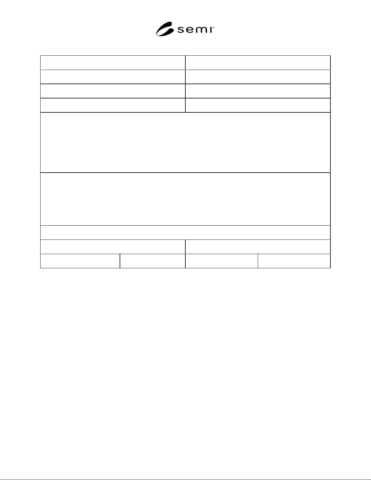
10.3 See Table 2 for a sample blank test data form.
SEMI S9-1101 © SEMI 1995, 20017
Table 2 Sample Blank Test Data Form
Manufacturer: Tester’s Name:
Name of Equipment: Model No.:
Serial No.: Date:
Location of Test Performed:
(Test Name)
Test Method:
Test Result:
Tester: Reviewed:
Equipment Used: Model No.: Serial No.: Last Date Calibrated:
11 Related Documents
11.1 SEMI Standards
SEMI S1 — Safety Guidelines for Equipment Safety Labels
11.2 IEC Documents
IEC 60204 — Safety of Machinery – Electrical equipment of Machines, Part 1: General Requirements
IEC 60950 — Safety of Information Technology Equipment
NOTICE: SEMI makes no warranties or representations as to the suitability of the guidelines set forth herein for
any particular application. The determination of the suitability of the guideline is solely the responsibility of the
user. Users are cautioned to refer to manufacturer's instructions, product labels, product data sheets, and other
relevant literature, respecting any materials or equipment mentioned herein. These guidelines are subject to change
without notice.
By publication of this guideline, Semiconductor Equipment and Materials International (SEMI) takes no position
respecting the validity of any patent rights or copyrights asserted in connection with any item mentioned in this
guideline. Users of this guideline are expressly advised that determination of any such patent rights or copyrights,
and the risk of infringement of such rights are entirely their own responsibility.
Copyright by SEMI® (Semiconductor Equipment and Materials
International), 3081 Zanker Road, San Jose, CA 95134. Reproduction o
f
the contents in whole or in part is forbidden without express written
consent of SEMI.