semi合集-English.pdf - 第803页
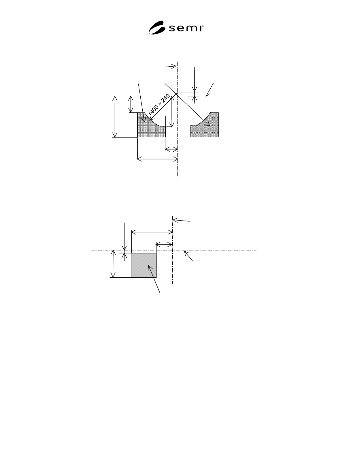
SEMI E110-1102 © SEMI 2001, 2002 5 Table 3 Dimensions of Switch Placemen t Volume Symbol Used Figure Value Specified Reference Measured From Remarks r400 3 240 mm (9.45 in) y67 in front of no minal wa fer center line Equ…
SEMI E110-1102 © SEMI 2001, 2002 4
Y67=25
(Refer to
SEMI E47.1.)
Bilateral Datum Plane
C
L
Facial Datum Plane
Switch placement volume
x404=245
y400=100
x403=75
y401=250
y402=190
Figure 3
Top View of Switch Placement Volume
z405=165
Horizontal Datum Plane
C
L
Facial Datum Plane
Switch placement volume
y400=100
z404=15
y401=250
Figure 4
Side View of Switch Placement Volume
SEMI E110-1102 © SEMI 2001, 2002 5
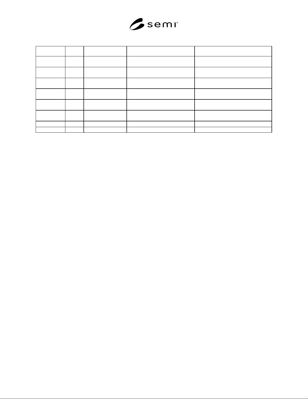
Table 3 Dimensions of Switch Placement Volume
Symbol Used Figure Value Specified Reference Measured From Remarks
r400 3 240 mm (9.45 in)
y67 in front of nominal wafer
center line
Equal to the maximum value of r67
defined in SEMI E47.1
x403 3 75 mm (2.95 in.) bilateral datum plane
-
x404 3 245 mm (9.65 in.) bilateral datum plane
-
y400 3,4 100 mm (3.94 in)
facial datum plane (as shown in
Figure 1 of SEMI E15.1)
-
y401 3,4 250 mm(9.843 in)
facial datum plane (as shown in
Figure 1 of SEMI E15.1)
Equal to the maximum value of D
defined in SEMI E15.1
y402 3 190 mm (7.48 in)
facial datum plane (as shown in
Figure 1 of SEMI E15.1)
Equal to the maximum value of y53
defined in SEMI E47.1
z404 4
15 mm (0.59 in.)
horizontal datum plane
-
z405 4 165 mm (6.50 in.) horizontal datum plane -
6 Related Documents
6.1 SEMI Standards
SEMI E62 — Provisional Specification for 300 mm Front-Opening Interface Mechanical Standard (FIMS)
SEMI E63 — Mechanical Specification for 300 mm Box Opener/Loader to Tool Standard (BOLTS-M) Interface
SEMI E92 — Provisional Specification for 300 mm Light Weight and Compact Box Opener/Loader to Tool-
Interoperability Standard (BOLTS/Light)
SEMI S8 — Safety Guidelines for Ergonomics Engineering of Semiconductor Manufacturing Equipment
NOTICE: SEMI makes no warranties or representations as to the suitability of the standards set forth herein for any
particular application. The determination of the suitability of the standard is solely the responsibility of the user.
Users are cautioned to refer to manufacture' s instructions, product labels, product data sheets, and other relevant
literature, respecting any materials or equipment mentioned herein. These standards are subject to change without
notice.
By publications of this standard, Semiconductor Equipment and Materials International (SEMI) takes no position
respecting the validity of any patent rights or copyrights asserted in connection with any items mentioned in this
standard. Users of this standard are expressly advised that determination of any such patent rights or copyrights, and
the risk of infringement of such rights are entirely their own responsibility.
Copyright by SEMI® (Semiconductor Equipment and Materials
International), 3081 Zanker Road, San Jose, CA 95134. Reproduction o
f
the contents in whole or in part is forbidden without express written
consent of SEMI.

SEMI E111-0305 © SEMI 2001, 2005 1
SEMI E111-0305
PROVISIONAL MECHANICAL SPECIFICATION FOR A 150 mm
RETICLE SMIF POD (RSP150) USED TO TRANSPORT AND STORE A 6
INCH RETICLE
This specification was technically approved by the Global Physical Interfaces and Carriers Committee and is
the direct responsibility of the North American Physical Interfaces and Carriers Committee. Current edition
approved by the North American Regional Standards Committee on December 10, 2004. Initially available
at www.semi.org February 2005; to be published March 2005. Originally published November 2001; last
published November 2004.
1 Purpose
1.1 This standard specifies the 150 mm Reticle SMIF Pod (RSP150) used to transport and store a 6 inch reticle in
an integrated circuit (IC) manufacturing facility.
2 Scope
2.1 This standard is intended to set an appropriate level of specification that places minimal limits on innovation
while ensuring modularity and inter- changeability at all mechanical interfaces. Most of the requirements given in
this specification are in the form of maximum or minimum dimensions with very few required surfaces. Only the
physical interfaces for the RSP150 are specified; no materials requirements or micro-contamination limits are given
in this specification.
2.2 The pellicle exclusion volume of this specification accommodates pellicles which extend the full length of the
reticle and up to a maximum pellicle width of 124 mm.
2.3 The RSP150 has the following components, sub-components, and other features. A “” symbol indicates
components or features which are required and a “” symbol indicates components or features which are optional.
Top
robotic handling flange
Interior
supports for one 6 inch reticle
reticle capture
reticle contact surfaces
end-effector exclusion volumes
2 safety rail exclusion volumes
pellicle exclusion volumes
lateral constraints
2 reticle backstops
Sides
2 side handling flanges on the sides parallel to the bi-lateral reference plane
2 side handling exclusion volumes
RFID placement zone
Bottom
door compatible with SMIF as defined in SEMI E19.3