semi合集-English.pdf - 第6026页
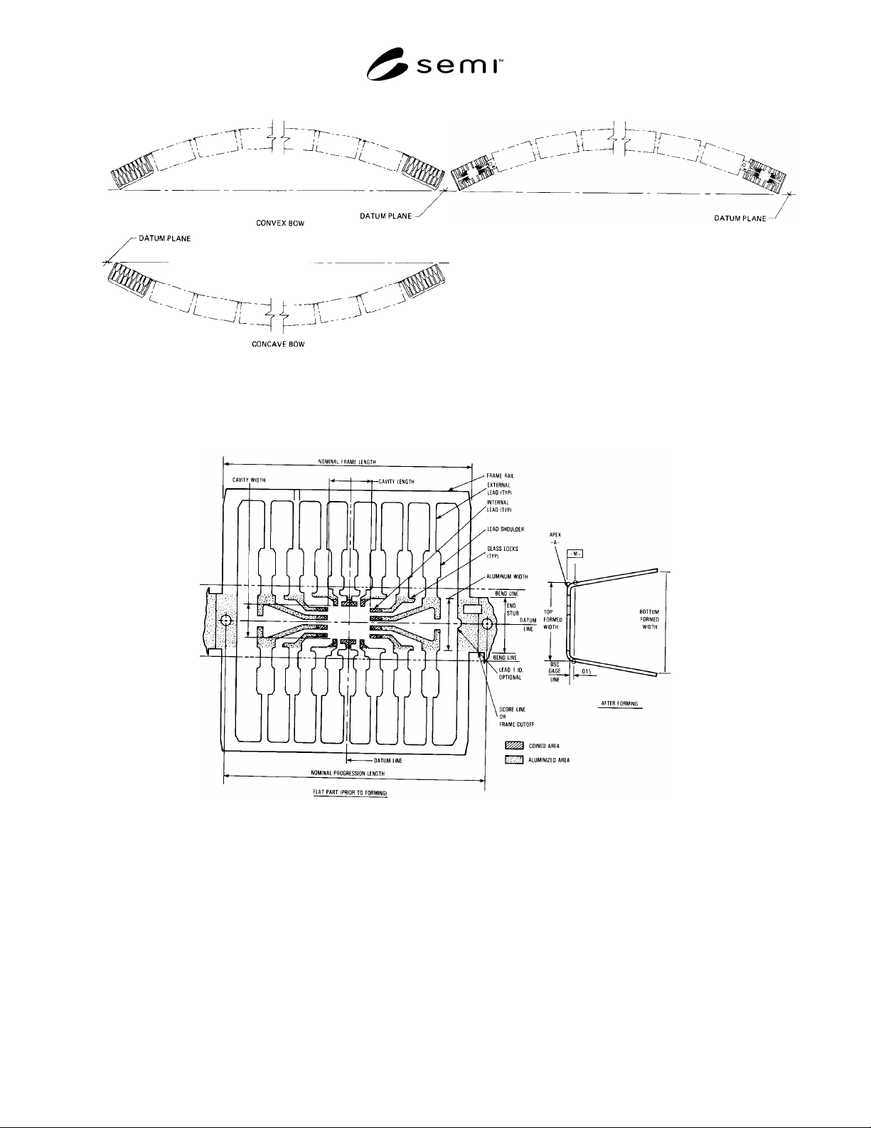
SEMI G2-94 © SEMI 1 994 6 Figure 1 Bow Figure 2 Camber Figure 3 Stamped Leadframe Terminology
SEMI G2-94 © SEMI 19945
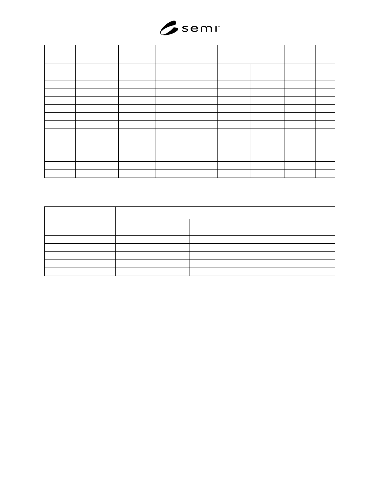
Description Cavity Length Cavity Width Lead-Formed Width, Top
Bond Finger Layout
End vs. Side
Nominal
Progression Unit
24SD3M 0.430 ± 0.010 0.180 ± 0.010 0.311 ± 0.003 8 4 1.510 in
10.92 ± 0.254 4.57 ± 0.254 7.90 ± 0.076 38.35 mm
24SD4M 0.210 ± 0.010 0.210 ± 0.010 0.411 ± 0.003 6 6 1.510 in
5.33 ± 0.254 5.33 ± 0.254 10.44 ± 0.076 38.35 mm
28MSI 0.260 ± 0.011 0.260 ± 0.011 0.611 ± 0.003 8 6 1.724 in
6.60 ± 0.279 6.60 ± 0.279 15.01 ± 0.076 43.79 mm
28LSI 0.325 ± 0.011 0.275 ± 0.011 0.611 ± 0.003 8 6 1.724 in
8.26 ± 0.279 6.99 ± 0.279 15.01 ± 0.076 43.79 mm
28VLSI 0.420 ± 0.011 0.280 ± 0.011 0.611 ± 0.003 8 6 1.724 in
10.67 ± 0.279 7.11 ± 0.279 15.01 ± 0.076 43.79 mm
40MSI 0.270 ± 0.012 0.260 ± 0.012 0.611 ± 0.003 10 10 2.300 in
6.86 ± 0.305 6.60 ± 0.305 15.01 ± 0.076 58.42 mm
40LSI 0.375 ± 0.012 0.295 ± 0.012 0.611 ± 0.003 12 8 2.300 in
9.53 ± 0.305 7.49 ± 0.305 15.01 ± 0.076 58.42 mm
NOTE: While a 0.311 top form is still currently being used, numerous users have changed to a 0.314 top form to prevent interference between the
Cer-DIP base and leadframe.
Table 2
Leads Planarity Coplanarity
8–14–16 +0.003"/–0.004" (+ 0.076 mm/–0.102 mm) 0.004" (0.102 mm)
18 +0.004"/–0.005" (+0.102 mm/–0.127 mm) 0.005" (0.127 mm)
20 +0.004"/–0.005" (+0.102 mm/–0.127 mm) 0.006" (0.152 mm)
22 +0.004"/–0.006" (+0.102 mm/–0.152 mm) 0.006" (0.152 mm)
24 +0.004"/–0.006" (+0.102 mm/–0.152 mm) 0.007" (0.178 mm)
28 +0.005"/–0.007" (+0.127 mm/–0.178 mm) 0.008" (0.203 mm )
40 +0.006"/–0.008" (+0.152 mm/–0.203 mm) 0.010" (0.254 mm)
SEMI G2-94 © SEMI 1994 6
Figure 1
Bow
Figure 2
Camber
Figure 3
Stamped Leadframe Terminology
SEMI G2-94 © SEMI 19947
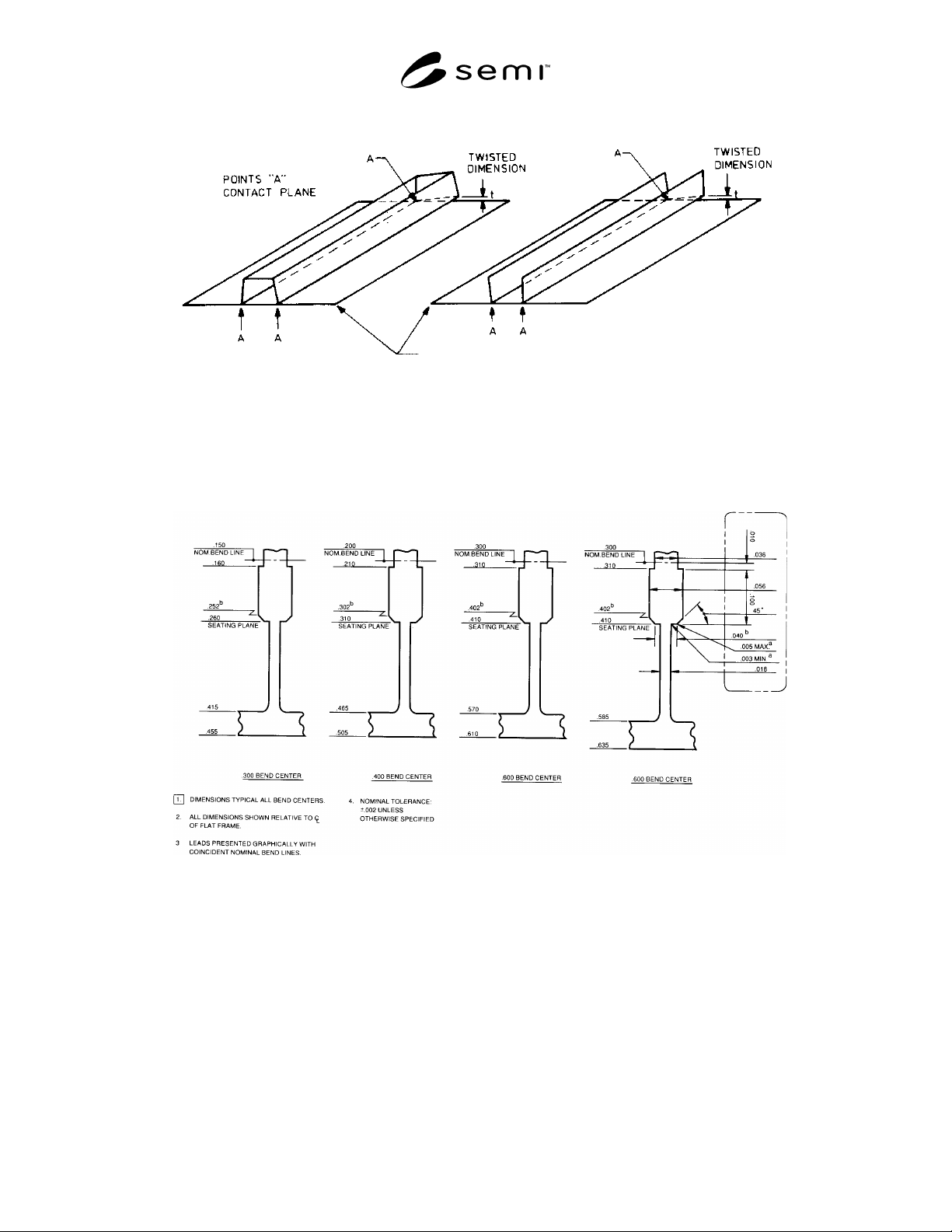
METHOD #1
METHOD #2
REF PLANE
Figure 4
Twist Strip
Using surface plate, establish a reference plane the whole length of the frame strip. Place frame strip, either method
1 or 2, whichever method gives a 3 point contact with reference plane A, using thickness gauges to determine height
between reference plane and 4th point noted as t. This measurement will determine frame twist over entire length.
Figure 5
Standoff Lead Length